Lexus NX: Short to +B in Outer Mirror Indicator(Master) (C1AB0)
DESCRIPTION
This DTC is stored when the blind spot monitor sensor LH detects a +B short in the outer rear view mirror indicator LH.
| DTC No. | Detection Item | DTC Detection Condition | Trouble Area | Note |
|---|---|---|---|---|
| C1AB0 | Short to +B in Outer Mirror Indicator(Master) | Both of the following conditions are met:
|
| - |
WIRING DIAGRAM
w/o Retract Mirror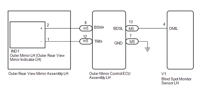 w/ Retract Mirror
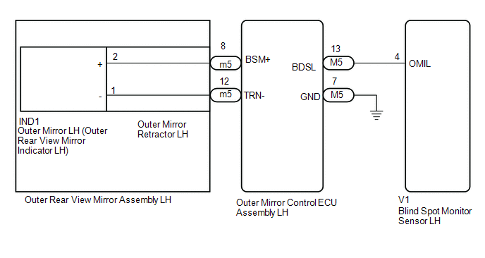
CAUTION / NOTICE / HINT
NOTICE:
When checking for DTCs, make sure that the blind spot monitor main switch (combination switch assembly) is on.
PROCEDURE
| 1. | CHECK DTC |
(a) Clear the DTCs.
Click here .gif)
(b) Recheck for DTCs and check if the same DTC is output again.
Body Electrical > Blind Spot Monitor Master > Trouble CodesOK:
DTC C1AB0 is not output.
| OK | .gif) | USE SIMULATION METHOD TO CHECK |
|
.gif)
| 2. | CHECK HARNESS AND CONNECTOR (BLIND SPOT MONITOR SENSOR LH - OUTER MIRROR LH) |
| (a) Disconnect the blind spot monitor sensor LH connector. |
|
(b) Measure the voltage according to the value(s) in the table below.
Standard Voltage:
| Tester Connection | Switch Condition | Specified Condition |
|---|---|---|
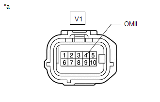
| V1-4 (OMIL) - Body ground | Power switch on (IG) | Below 1 V |
| OK | | REPLACE BLIND SPOT MONITOR SENSOR LH |
|
| 3. | CHECK HARNESS AND CONNECTOR (BLIND SPOT MONITOR SENSOR LH - OUTER REAR VIEW MIRROR ASSEMBLY LH) |
| (a) Disconnect the blind spot monitor sensor LH connector. |
|
(b) Disconnect the IND1 outer mirror LH connector.
(c) Measure the voltage according to the value(s) in the table below.
Standard Voltage:
| Tester Connection | Switch Condition | Specified Condition |
|---|---|---|
| V1-4 (OMIL) - Body ground | Power switch on (IG) | Below 1 V |
| OK | | REPLACE OUTER MIRROR LH |
|
| 4. | CHECK HARNESS AND CONNECTOR (BLIND SPOT MONITOR SENSOR LH - OUTER MIRROR CONTROL ECU ASSEMBLY LH) |
| (a) Disconnect the blind spot monitor sensor LH connector. |
|
(b) Disconnect the m5 outer mirror control ECU assembly LH connector.
(c) Measure the voltage according to the value(s) in the table below.
Standard Voltage:
| Tester Connection | Switch Condition | Specified Condition |
|---|---|---|
| V1-4 (OMIL) - Body ground | Power switch on (IG) | Below 1 V |
| Result | Proceed to |
|---|---|
| OK (w/o Retract Mirror) | A |
| OK (w/ Retract Mirror) | B |
| NG | C |
| A | | REPLACE OUTER REAR VIEW MIRROR ASSEMBLY LH |
| B | | REPLACE OUTER MIRROR RETRACTOR LH |
|
| 5. | CHECK HARNESS AND CONNECTOR (BLIND SPOT MONITOR SENSOR LH - OUTER MIRROR CONTROL ECU ASSEMBLY LH) |
| (a) Disconnect the blind spot monitor sensor LH connector. |
|
(b) Disconnect the M5 outer mirror control ECU assembly LH connector.
(c) Measure the voltage according to the value(s) in the table below.
Standard Voltage:
| Tester Connection | Switch Condition | Specified Condition |
|---|---|---|
| V1-4 (OMIL) - Body ground | Power switch on (IG) | Below 1 V |
| OK | | REPLACE OUTER MIRROR CONTROL ECU ASSEMBLY LH |
| NG | | REPAIR OR REPLACE HARNESS OR CONNECTOR |
READ NEXT:
 Short to +B in Outer Mirror Indicator(Slave) (C1AB1)
DESCRIPTION This DTC is stored when the blind spot monitor sensor RH detects a +B short in the outer rear view mirror indicator RH. DTC No. Detection Item DTC Detection Condition Trouble Area
Short to GND in Outer Mirror Indicator(Master) (C1AB2)
DESCRIPTION This DTC is stored when the blind spot monitor sensor LH detects a ground short in the outer rear view mirror indicator LH. DTC No. Detection Item DTC Detection Condition Trouble
Short to GND in Outer Mirror Indicator(Slave) (C1AB3)
DESCRIPTION This DTC is stored when the blind spot monitor sensor RH detects a ground short in the outer rear view mirror indicator RH. DTC No. Detection Item DTC Detection Condition Trouble
SEE MORE:
Lost Communication with Brake System Control Module (U0129,U0140,U0293)
DESCRIPTION These DTCs are stored when the CAN communication system is malfunctioning. DTC No. Detection Item DTC Detection Condition Trouble Area U0129 Lost Communication with Brake System Control Module The vehicle approaching speaker controller does not receive data from the skid
Open in One Side of Bus 5 Branch Line
DESCRIPTION When the CAN bus main lines are normal (no open, short to ground, short to +B or short between lines) and there is an ECU or sensor on the "Communication Bus Check" screen that is indicated as not communicating or whose connection status on the "Communication Bus Check" screen changes in
