Lexus NX: Sliding Roof Switch Assembly
Components
COMPONENTS
ILLUSTRATION
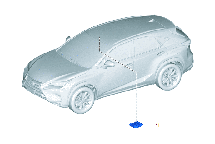
| *1 | MAP LIGHT ASSEMBLY (SLIDING ROOF SWITCH ASSEMBLY) | - | - |
Inspection
INSPECTION
PROCEDURE
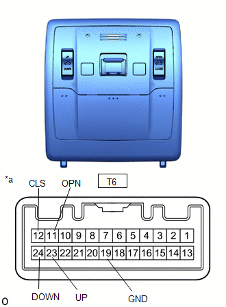
1. INSPECT MAP LIGHT ASSEMBLY (SLIDING ROOF SWITCH ASSEMBLY)
| (a) Measure the resistance according to the value(s) in the table below. Standard Resistance:
If the result is not as specified, replace the map light assembly (sliding roof switch assembly). |
|
Removal
REMOVAL
PROCEDURE
1. REMOVE MAP LIGHT ASSEMBLY (SLIDING ROOF SWITCH ASSEMBLY)
Click here .gif)
Installation
INSTALLATION
PROCEDURE
1. INSTALL MAP LIGHT ASSEMBLY (SLIDING ROOF SWITCH ASSEMBLY)
Click here .gif)
READ NEXT:
 Parts Location
PARTS LOCATION ILLUSTRATION *1 FRONT DOOR COURTESY LIGHT SWITCH ASSEMBLY LH *2 MAP LIGHT ASSEMBLY *3 SLIDE ROOF SWITCH *4 SLIDING ROOF DRIVE GEAR SUB-ASSEMBLY
- SLIDING ROOF ECU
System Diagram
SYSTEM DIAGRAM
SEE MORE:
How To Proceed With Troubleshooting
CAUTION / NOTICE / HINT HINT:
Use the following procedures to troubleshoot the clock system.
*: Use the Techstream.
PROCEDURE 1. VEHICLE BROUGHT TO WORKSHOP
NEXT 2. CUSTOMER PROBLEM ANALYSIS AND SYMPTOM CHECK
NEXT 3. INSPECT AUXILIARY
Components
COMPONENTS ILLUSTRATION *A w/ Hands Free Power Back Door - - *1 NO. 2 LUGGAGE ROOM WIRE *2 REAR CENTER ULTRASONIC SENSOR *3 REAR CENTER ULTRASONIC SENSOR RETAINER *4 REAR CORNER ULTRASONIC SENSOR *5 REAR CORNER ULTRASONIC SENSOR RETAINER - - ● Non-reus
