Lexus NX: Speedometer Malfunction
DESCRIPTION
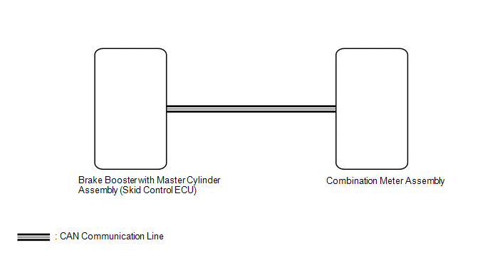
The combination meter assembly receives vehicle speed signals from the brake booster with master cylinder assembly (skid control ECU) via the CAN communication line. The wheel speed sensors output voltages that vary according to the vehicle speed. The brake booster with master cylinder assembly (skid control ECU) supplies power to the wheel speed sensors. The brake booster with master cylinder assembly (skid control ECU) calculates the vehicle speed based on the pulses of the voltage.
WIRING DIAGRAM
CAUTION / NOTICE / HINT
NOTICE:
- When replacing the combination meter assembly, make sure to replace it with a new one.
-
If the vehicle speed is outside the allowable range when tested, perform the operation check.
Click here
.gif)
HINT:
Before starting the following inspection, check tire size and tire air pressure.
PROCEDURE
| 1. | CHECK FOR DTC (CAN COMMUNICATION SYSTEM) |
(a) Check for DTCs.
Click here
OK:
No DTCs are output.
| NG | .gif) | GO TO CAN COMMUNICATION SYSTEM |
|
.gif)
| 2. | CHECK FOR DTC (ELECTRONICALLY CONTROLLED BRAKE SYSTEM) |
(a) Check for DTCs.
Click here
OK:
No DTCs are output.
| NG | | GO TO ELECTRONICALLY CONTROLLED BRAKE SYSTEM |
|
| 3. | PERFORM ACTIVE TEST USING TECHSTREAM (SPEED METER OPERATION) |
(a) Using the Techstream, perform the Active Test.
Click here
| Tester Display | Measurement Item | Control Range | Diagnostic Note |
|---|---|---|---|
| Speed Meter Operation | Speedometer |
| There is a deviation in the values displayed on the speedometer display (Control range → Speedometer) with km/h units:
with mph units:
|
| Tester Display |
|---|
| Speed Meter Operation |
OK:
Speedometer indication is normal.
| NG | | REPLACE COMBINATION METER ASSEMBLY |
|
| 4. | READ VALUE USING TECHSTREAM (VEHICLE SPEED METER) |
(a) Using the Techstream, read the Data List.
Click here
| Tester Display | Measurement Item | Range | Normal Condition | Diagnostic Note |
|---|---|---|---|---|
| Vehicle Speed Meter | Vehicle speed | Min.: 0 km/h (0 mph), Max.: 255 km/h (158 mph) | Almost the same as actual vehicle speed | - |
| Tester Display |
|---|
| Vehicle Speed Meter |
HINT:
- When the Data List values of the ECUs match, an internal malfunction of the combination meter assembly is suspected.
- When the Data List values of the ECUs do not match, a signal output error of the brake booster with master cylinder assembly (skid control ECU) or an internal malfunction of the combination meter assembly is suspected.
OK:
Vehicle speed displayed on the Techstream is almost the same as the actual vehicle speed measured using a speedometer tester (calibrated chassis dynamometer).
| OK | | REPLACE COMBINATION METER ASSEMBLY |
|
| 5. | READ VALUE USING TECHSTREAM (VEHICLE SPEED) |
(a) Using the Techstream, read the Data List.
Click here
| Tester Display | Measurement Item | Normal Condition | Reference Value | Diagnostic Note |
|---|---|---|---|---|
| Vehicle Speed | Vehicle speed | Min.: 0 km/h (0 mph), Max.: 326 km/h (202 mph) | Almost the same as actual vehicle speed | - |
| Tester Display |
|---|
| Vehicle Speed |
OK:
Vehicle speed displayed on the Techstream is almost the same as the actual vehicle speed measured using a speedometer tester (calibrated chassis dynamometer).
| NG | | REPLACE BRAKE BOOSTER WITH MASTER CYLINDER ASSEMBLY (SKID CONTROL ECU) |
|
| 6. | CHECK COMBINATION METER ASSEMBLY |
(a) Replace the combination meter assembly.
Click here
(b) Check that the operation of the speedometer returns to normal.
OK:
The operation of the speedometer returns to normal.
| OK | | END (COMBINATION METER ASSEMBLY IS DEFECTIVE) |
| NG | | REPLACE BRAKE BOOSTER WITH MASTER CYLINDER ASSEMBLY (SKID CONTROL ECU) |
READ NEXT:
 Tachometer Malfunction
DESCRIPTION In this circuit, the combination meter assembly receives engine speed signals from the hybrid vehicle control ECU via the CAN communication system. The combination meter assembly displays
Fuel Receiver Gauge Display Malfunction
DESCRIPTION OPERATION The combination meter assembly uses the fuel injection volume signal from the ECM, fuel sender gauge assembly to detect the amount of fuel remaining in the fuel tank assembly. Ea
Engine Coolant Temperature Receiver Gauge Malfunction
DESCRIPTION In this circuit, the combination meter assembly receives engine coolant temperature signals from the ECM via the CAN communication system. The combination meter assembly displays the engin
SEE MORE:
Lost Communication with Cruise Control Front Distance Range Sensor Missing Message (U023587)
DESCRIPTION The forward recognition camera is connected to the millimeter wave radar sensor assembly via the CAN communication line. When the signal from the millimeter wave radar sensor assembly is interrupted, the forward recognition camera outputs U023587. DTC No. Detection Item DTC Detect
Inspection
INSPECTION PROCEDURE 1. INSPECT NO. 3 BATTERY SERVICE COVER BOARD (a) Inspect the No. 3 battery service cover board. (1) Visually inspect the filter. Standard: No deformation or cracks. If the result is not as specified, replace the No. 3 battery service cover board. (2) Clean the filter. Standa
