Lexus NX: Startability Malfunction (P1604)
DESCRIPTION
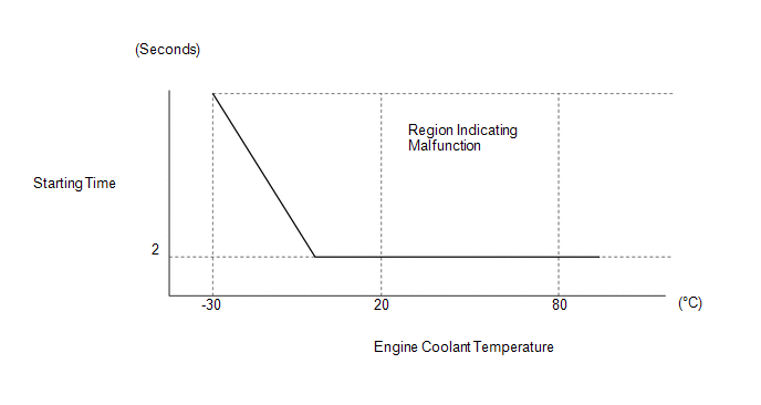
If the engine does not start or it takes a long time for the engine to start, despite the ECM receiving the engine start request signal from the hybrid vehicle control ECU via CAN communication, this DTC will be stored.
Read freeze frame data using the Techstream. The ECM records vehicle and driving condition information as freeze frame data the moment a DTC is stored. When troubleshooting, freeze frame data can be helpful in determining whether the vehicle was moving or stationary, whether the engine was warmed up or not, whether the air fuel ratio was lean or rich, as well as other data recorded at the time of a malfunction.
| DTC No. | Detection Item | DTC Detection Condition | Trouble Area | MIL | Memory |
|---|---|---|---|---|---|
| P1604 | Startability Malfunction | Either of the following conditions is met (1 trip detection logic):
| - | Does not come on | DTC Stored |
CAUTION / NOTICE / HINT
HINT:
-
In contrast to normal malfunction diagnosis for components, circuits and systems, DTC P1604 is used to determine the malfunctioning area from the problem symptoms and freeze frame data when the user mentions problems such as starting difficulty.
As these DTCs can be stored as a result of certain user actions, even if these DTCs are output, if the customer makes no mention of problems, clear these DTCs without performing any troubleshooting and return the vehicle to the customer.
- If any DTCs other than P1604 are output, troubleshoot those DTCs first.
- Since DTC P1604 is different from other DTCs, the following procedure is shown as a reference.
- Read freeze frame data using the Techstream. Freeze frame data records engine conditions when a malfunction occurs. This information can be useful when troubleshooting.
-
When confirming the freeze frame data, be sure to check all 5 sets of freeze frame data.
Click here
.gif)
- When confirming freeze frame data, if there are multiple items related to the cause of the malfunction, perform troubleshooting for all related items.
- Try to start the vehicle under the conditions recorded in the freeze frame data which were present when the malfunction occurred. Confirm the data at this time and compare it with the freeze frame data.
- If the malfunction does not reoccur, carefully check the vehicle conditions from when the malfunction occurred using freeze frame data.
- When performing inspections, jiggle the relevant wire harnesses and connectors in an attempt to reproduce malfunctions that do not always occur.
PROCEDURE
| 1. | CHECK ANY OTHER DTCS OUTPUT (IN ADDITION TO DTC P1604) |
(a) Connect the Techstream to the DLC3.
(b) Turn the power switch on (IG).
(c) Turn the Techstream on.
(d) Enter the following menus: Powertrain / Engine and ECT / Trouble Codes.
(e) Read the DTCs.
Click here
| Result | Proceed to |
|---|---|
| DTC P1604 is output | A |
| DTC P1604 and other DTCs are output | B |
HINT:
If any DTCs other than P1604 are output, troubleshoot those DTCs first.
| B | .gif) | GO TO DTC CHART |
|
.gif)
| 2. | CHECK FREEZE FRAME DATA |
(a) Turn the Techstream on.
(b) Check the following freeze frame data to see the state of the auxiliary battery when the freeze frame data was recorded.
Confirmation Item| Battery Voltage |
(c) Check the following freeze frame data to see if the engine was cranking when the freeze frame data was recorded.
Confirmation Item| Engine Speed |
| Engine Speed (Starter Off) |
(d) Check the following freeze frame data to check temperature data recorded when the engine did not start normally.
Confirmation Item| Coolant Temp |
| Intake Air |
| Engine Oil Temperature |
| Ambient Temp for A/C |
(e) Check the following freeze frame data to see the engine operating conditions recorded when the engine started.
Confirmation Item| MAF |
| Throttle Position |
| ISC Flow |
| ISC Position |
| MAP |
| EGR Step Position |
(f) Check the following freeze frame data to see before the engine did not start normally.
Confirmation Item| Run Dist of Previous Trip |
| Previous Trip Intake Temp |
| Previous Trip Eng Oil Temp |
| Previous Trip Ambient Temp |
(g) Use this information to perform a simulation test.
(h) Compare the "Normal Condition" information in the Data List table (reference values) with the freeze frame data listed above and with the simulation test results to determine the problem cause.
| Result | Proceed to |
|---|---|
| The problem cause can be determined | A |
| The problem cause cannot be determined | B |
| A | | REPAIR OR REPLACE MALFUNCTIONING PARTS |
| B | | CHECK FOR INTERMITTENT PROBLEMS |
READ NEXT:
 Rough Idling (P1605)
DESCRIPTION When the engine is idling stably under a low load, if the idle speed drops or becomes unstable, this DTC will be stored. Read freeze frame data using the Techstream. The ECM records vehicl
Throttle Actuator Control Motor Circuit Low (P2102,P2103)
DESCRIPTION The throttle actuator is operated by the ECM and opens and closes the throttle valve using gears. The opening angle of the throttle valve is detected by the throttle position sensor, which
Throttle / Pedal Position Sensor "A" Minimum Stop Performance (P2109)
DESCRIPTION The idle speed is controlled by the Electronic Throttle Control System (ETCS). The ETCS is comprised of a throttle actuator, which operates the throttle valve, and a throttle position sens
SEE MORE:
Drive Motor "A" Inverter Performance (P0A78-113)
DTC SUMMARY MALFUNCTION DESCRIPTION This DTC indicates that a large current flowed through the inverter for the motor. The cause of this malfunction may be one of the following: Area Main Malfunction Description Step Inverter low-voltage circuit The connectors are not connected properly
Components
COMPONENTS ILLUSTRATION *1 FRONT DOOR INSIDE HANDLE BEZEL PLUG LH *2 FRONT DOOR TRIM BOARD SUB-ASSEMBLY LH *3 FRONT DOOR TRIM COVER LH *4 OUTER MIRROR INSTALL HOLE COVER LH *5 OUTER REAR VIEW MIRROR ASSEMBLY LH *6 POWER WINDOW REGULATOR MASTER SWITCH ASSEMBLY WITH FRONT
