Lexus NX: Steering Angle Sensor
Components
COMPONENTS
ILLUSTRATION
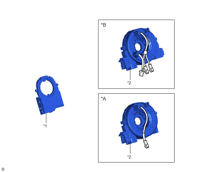
| *A | w/o Steering Heater | *B | w/ Steering Heater |
| *1 | STEERING SENSOR | *2 | SPIRAL CABLE SUB-ASSEMBLY |
Removal
REMOVAL
PROCEDURE
1. REMOVE SPIRAL W/SENSOR CABLE SUB-ASSEMBLY
Click here .gif)
2. REMOVE STEERING SENSOR
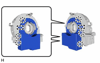
| (a) Disengage the 6 claws and 2 pins, and remove the steering sensor from the spiral cable sub-assembly. NOTICE: Do not damage the claws and pins of the spiral cable sub-assembly. |
|
Installation
INSTALLATION
PROCEDURE
1. INSTALL STEERING SENSOR
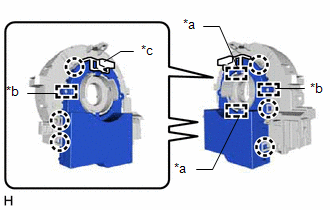
| (a) Align the 2 pins and 2 guides, and engage the 6 claws to install the steering sensor to the spiral cable sub-assembly. NOTICE:
|
|
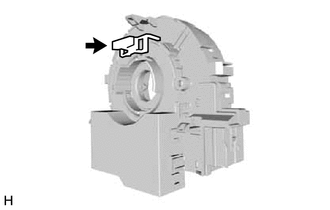
| (b) Remove the lock pin from the steering sensor. |
|
2. INSTALL SPIRAL W/SENSOR CABLE SUB-ASSEMBLY
Click here .gif)
READ NEXT:
 Components
COMPONENTS ILLUSTRATION *1 CENTER INSTRUMENT CLUSTER FINISH PANEL ASSEMBLY *2 INSTRUMENT SIDE PANEL LH *3 INSTRUMENT SIDE PANEL RH *4 LOWER NO. 1 INSTRUMENT PANEL FINISH PANEL
Removal
REMOVAL PROCEDURE 1. REMOVE CONSOLE ARMREST ASSEMBLY Click here 2. REMOVE REAR UPPER CONSOLE PANEL Click here 3. REMOVE UPPER NO. 2 CONSOLE PANEL GARNISH Click here 4. REMOVE UPPER NO. 1 C
SEE MORE:
Throttle / Pedal Position Sensor / Switch "D" Circuit (P2120-152,...,P2138-154)
DESCRIPTION The accelerator pedal position sensor is mounted on the accelerator pedal to detect how much the pedal is depressed. This is a non-contact sensor with Hall elements. There are 2 outputs from the sensor. One is used to detect the accelerator pedal position and the other is used as a confi
Installation
INSTALLATION CAUTION / NOTICE / HINT HINT:
Use the same procedure for the RH and LH sides.
The procedure described below is for the LH side.
PROCEDURE 1. INSTALL REAR LIGHT ASSEMBLY LH (a) Attach the guide, clip and pin to set the rear light assembly LH. *a Pin *b Gui
© 2016-2024 Copyright www.lexunx.com
