Lexus NX: Steering Heater Switch
Inspection
INSPECTION
PROCEDURE
1. REMOVE NO. 2 COMBINATION SWITCH ASSEMBLY
Click here .gif)
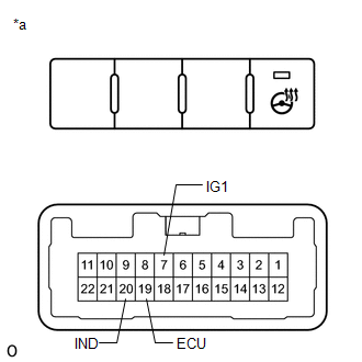
2. INSPECT NO. 2 COMBINATION SWITCH ASSEMBLY
| (a) Measure the voltage according to the value (s) in the table below. Standard Voltage:
HINT: As the circuit has a diode, perform the measurement in diode test mode, and do not mistake the polarity. |
|
(b) Measure the resistance according to the value (s) in the table below
Standard Resistance:
| Tester Connection | Switch Condition | Specified Condition |
|---|---|---|
| 7 (IG1) - 19 (ECU) | Steering heater switch is pushed | Below 1 Ω |
| Steering heater switch is not pushed | 10 kΩ or higher |
(c) Measure the voltage according to the value (s) in the table below.
(d) Measure the resistance according to the value (s) in the table below.
3. INSTALL NO. 2 COMBINATION SWITCH ASSEMBLY
Click here
READ NEXT:
 Precaution
PRECAUTION PRECAUTION FOR DISCONNECTING CABLE FROM NEGATIVE AUXILIARY BATTERY TERMINAL NOTICE:
After the power switch is turned off, there may be a waiting time before disconnecting the negative (-
Parts Location
PARTS LOCATION ILLUSTRATION *1 NO. 1 ENGINE ROOM RELAY BLOCK - IG2-MAIN RELAY - IG2-MAIN FUSE - STRG LOCK FUSE - - ILLUSTRATION *1 POWER SWITCH *2 INSTRUMENT PANEL JUNCTION BLOC
SEE MORE:
Customize Parameters
CUSTOMIZE PARAMETERS CUSTOMIZE POWER WINDOW CONTROL SYSTEM HINT: The following items can be customized. NOTICE:
When the customer requests a change in a function, first make sure that the function can be customized.
Be sure to make notes of the current settings before customizing.
When troubl
Open in IG Circuit (B242E)
DESCRIPTION This DTC is output when there is a problem in the power supply for the headlight ECU sub-assembly RH. The headlight ECU sub-assembly LH outputs DTC B242E. DTC No. Detection Item DTC Detection Condition Trouble Area B242E Open in IG Circuit IG circuit malfunction in the h
