Lexus NX: Steering Pad Switch Circuit
DESCRIPTION
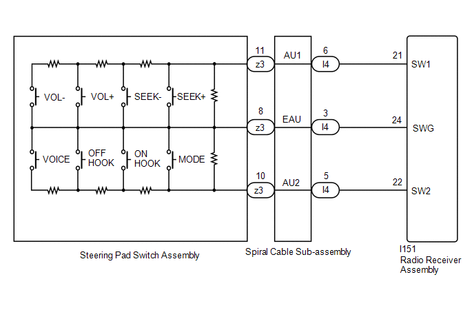
This circuit sends an operation signal from the steering pad switch assembly to the radio receiver assembly.
If there is an open in the circuit, the audio system cannot be operated using the steering pad switch assembly.
If there is a short in the circuit, the same condition as when a switch is continuously depressed occurs.
Therefore, the radio receiver assembly cannot be operated using the steering pad switch assembly, and also the radio receiver assembly itself cannot function.
WIRING DIAGRAM
CAUTION / NOTICE / HINT
NOTICE:
-
The vehicle is equipped with a Supplemental Restraint System (SRS) which includes components such as airbags. Before servicing (including removal or installation of parts), be sure to read the precaution for Supplemental Restraint System.
Click here
.gif)
-
After turning the power switch off, waiting time may be required before disconnecting the cable from the negative (-) auxiliary battery terminal.
Click here
-
When disconnecting and reconnecting the auxiliary battery.
Click here
HINT:
When disconnecting and reconnecting the auxiliary battery, there is an automatic learning function that completes learning when the respective system is used.
Click here
PROCEDURE
| 1. | INSPECT STEERING PAD SWITCH ASSEMBLY |
(a) Remove the steering pad switch assembly.
Click here
(b) Inspect the steering pad switch assembly.
Click here
| NG | .gif) | REPLACE STEERING PAD SWITCH ASSEMBLY |
|
.gif)
| 2. | INSPECT SPIRAL CABLE SUB-ASSEMBLY |
(a) Remove the spiral cable sub-assembly.
Click here
(b) Inspect the spiral cable sub-assembly.
Click here
| NG | | REPLACE SPIRAL CABLE SUB-ASSEMBLY |
|
| 3. | CHECK HARNESS AND CONNECTOR (RADIO RECEIVER ASSEMBLY - SPIRAL CABLE SUB-ASSEMBLY) |
(a) Disconnect the I151 radio receiver assembly connector.
(b) Disconnect the I4 spiral cable sub-assembly connector.
(c) Measure the resistance according to the value(s) in the table below.
Standard Resistance:
| Tester Connection | Condition | Specified Condition |
|---|---|---|
| I151-21 (SW1) - I4-6 (AU1) | Always | Below 1 Ω |
| I151-22 (SW2) - I4-5 (AU2) | Always | Below 1 Ω |
| I151-24 (SWG) - I4-3 (EAU) | Always | Below 1 Ω |
| I151-21 (SW1) - Body ground | Always | 10 kΩ or higher |
| I151-22 (SW2) - Body ground | Always | 10 kΩ or higher |
| OK | | PROCEED TO NEXT SUSPECTED AREA SHOWN IN PROBLEM SYMPTOMS TABLE |
| NG | | REPAIR OR REPLACE HARNESS OR CONNECTOR |
READ NEXT:
 Illumination Circuit
DESCRIPTION Power is supplied to the radio receiver assembly and steering pad switch assembly when the light control switch is in the tail or head position. WIRING DIAGRAM CAUTION / NOTICE / HINT NOT
Speaker Circuit
DESCRIPTION If there is a short in a speaker circuit, the stereo component amplifier assembly detects it and stops output to the speakers. As a result, sound cannot be heard from the speakers even if
Sound Signal Circuit between Radio Receiver and Stereo Jack Adapter
DESCRIPTION The No. 1 stereo jack adapter assembly sends the sound signal from an external device to the radio receiver assembly via this circuit. The sound signal that has been sent is amplified by t
SEE MORE:
Freeze Frame Data
FREEZE FRAME DATA DESCRIPTION (a) Whenever a front radar sensor system DTC is stored, the millimeter wave radar sensor assembly stores the current vehicle state as Freeze Frame Data. CHECK FREEZE FRAME DATA (a) Connect the Techstream to the DLC3. (b) Turn the power switch on (IG). (c) Turn the Techs
How To Proceed With Troubleshooting
CAUTION / NOTICE / HINT HINT:
Use the following procedure to troubleshoot the vehicle proximity notification system.
*: Use the GTS.
PROCEDURE 1. VEHICLE BROUGHT TO WORKSHOP
NEXT 2. CUSTOMER PROBLEM ANALYSIS AND SYMPTOM CHECK HINT:
In troubleshooting, co
