Lexus NX: Stop Light Relay Malfunction (C1380)
DESCRIPTION
Upon receiving the hill-start assist control, dynamic radar cruise control, brake hold control or trailer sway control operating signal from the skid control ECU (brake booster with master cylinder assembly), the relay contact turns on and the stop lights come on.
| DTC No. | Detection Item | INF Code | DTC Detection Condition | Trouble Area | Note |
|---|---|---|---|---|---|
| C1380 | Stop Light Relay Malfunction | 761 762 |
|
| - |
WIRING DIAGRAM
.png)
CAUTION / NOTICE / HINT
NOTICE:
-
When replacing the skid control ECU (brake booster with master cylinder assembly), perform initialization and calibration of the linear solenoid valve.
Click here
.gif)
- Inspect the fuses for circuits related to this system before performing the following procedure.
HINT:
When C1249 is output together with C1380, inspect and repair the trouble areas indicated by C1249 first.
Click here
PROCEDURE
| 1. | CHECK STOP LIGHT OPERATION |
(a) Check that the all stop lights come on when the brake pedal is depressed and go off when the brake pedal is released.
OK:
| Condition | Illumination Condition |
|---|---|
| Brake pedal depressed. | On |
| Brake pedal released. | Off |
| NG | .gif) | INSPECT LIGHTING SYSTEM |
|
.gif)
| 2. | READ VALUE USING TECHSTREAM (STOP LIGHT SWITCH ASSEMBLY) |
(a) Connect the Techstream to the DLC3.
(b) Turn the power switch on (IG).
(c) Select the Data List on the Techstream.
Click here
| Tester Display | Measurement Item | Range | Normal Condition | Diagnostic Note |
|---|---|---|---|---|
| Stop Light SW | Stop light switch assembly | ON or OFF | ON: Brake pedal depressed OFF: Brake pedal released | - |
| Tester Display |
|---|
| Stop Light SW |
(d) Check that the stop light switch assembly condition observed on the Techstream changes according to brake pedal operation.
OK:
The Techstream displays ON or OFF according to brake pedal operation.
| NG | | GO TO STEP 8 |
|
| 3. | PERFORM ACTIVE TEST USING TECHSTREAM (STOP LIGHT CONTROL ECU ASSEMBLY) |
(a) Select the Active Test on the Techstream.
Click here
| Tester Display | Measurement Item | Control Range | Diagnostic Note |
|---|---|---|---|
| Stop Light Relay | Stop light control ECU assembly (stop light control relay) | ECU (Relay) ON/OFF | Stop lights come on |
| Tester Display |
|---|
| Stop Light Relay |
(b) Perform the Active Test of the stop light control ECU assembly using the Techstream.
(c) Select the Data List on the Techstream.
Click here
| Tester Display | Measurement Item | Range | Normal Condition | Diagnostic Note |
|---|---|---|---|---|
| Stop Light Relay Output | Stop light control ECU assembly (stop light control relay) output | ON or OFF | ON: ECU (Relay) output on OFF: ECU (Relay) output off | - |
| Tester Display |
|---|
| Stop Light Relay Output |
(d) Check for stop light control ECU assembly operation using the Data List and stop light operation by performing the Active Test.
| Result | Proceed to |
|---|---|
| Data List content and stop light operation are normal. | A |
| Data List content and stop light operation are abnormal or Data List content is normal but stop lights do not turn on or off. | B |
| B | | GO TO STEP 6 |
|
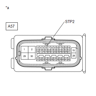
| 4. | CHECK HARNESS AND CONNECTOR (STP2 TERMINAL) |
| (a) Turn the power switch off. |
|
(b) Make sure that there is no looseness at the locking part and the connecting part of the connector.
(c) Disconnect the A57 skid control ECU (brake booster with master cylinder assembly) connector.
(d) Measure the voltage according to the value(s) in the table below.
Standard Voltage:
| Tester Connection | Condition | Specified Condition |
|---|---|---|
| A57-6 (STP2) - Body ground | Stop light switch assembly on (Brake pedal depressed) | 11 to 14 V |
| A57-6 (STP2) - Body ground | Stop light switch assembly off (Brake pedal released) | Below 1.5 V |
| NG | | REPAIR OR REPLACE HARNESS OR CONNECTOR (STP2 CIRCUIT) |
|
| 5. | RECONFIRM DTC |
(a) Reconnect the A57 skid control ECU (brake booster with master cylinder assembly) connector.
(b) Clear the DTCs.
Click here
(c) Turn the power switch on (READY).
(d) Perform a road test.
(e) Check if the same DTC is output.
Click here
| Result | Proceed to |
|---|---|
| DTC C1380 is not output. | A |
| DTC C1380 is output. | B |
| A | | USE SIMULATION METHOD TO CHECK |
| B | | REPLACE BRAKE BOOSTER WITH MASTER CYLINDER ASSEMBLY |
| 6. | INSPECT STOP LIGHT CONTROL ECU ASSEMBLY |
(a) Turn the power switch off.
(b) Check the stop light control ECU assembly.
Click here
OK:
The stop light control ECU assembly is normal.
| NG | | REPLACE STOP LIGHT CONTROL ECU ASSEMBLY |
|
| 7. | CHECK HARNESS AND CONNECTOR (BRAKE BOOSTER WITH MASTER CYLINDER ASSEMBLY - STOP LIGHT CONTROL ECU ASSEMBLY) |
(a) Make sure that there is no looseness at the locking part and the connecting part of the connectors.
(b) Disconnect the A57 skid control ECU (brake booster with master cylinder assembly) connector.
(c) Disconnect the A3 stop light control ECU assembly connector.
(d) Measure the resistance according to the value(s) in the table below.
Standard Resistance:
| Tester Connection | Condition | Specified Condition |
|---|---|---|
| A57-3 (STPO) -A3-9 (ACC) | Always | Below 1 Ω |
| A57-3 (STPO) or A3-9 (ACC) - Body ground | Always | 10 kΩ or higher |
| OK | | REPLACE BRAKE BOOSTER WITH MASTER CYLINDER ASSEMBLY |
| NG | | REPAIR OR REPLACE HARNESS OR CONNECTOR |
| 8. | CHECK HARNESS AND CONNECTOR (STP TERMINAL) |
| (a) Turn the power switch off. |
|
.png)
(b) Make sure that there is no looseness at the locking part and the connecting part of the connector.
(c) Disconnect the A57 skid control ECU (brake booster with master cylinder assembly) connector.
(d) Measure the voltage according to the value(s) in the table below.
Standard Voltage:
| Tester Connection | Condition | Specified Condition |
|---|---|---|
| A57-33 (STP) - Body ground | Stop light switch assembly on (Brake pedal depressed) | 11 to 14 V |
| A57-33 (STP) - Body ground | Stop light switch assembly off (Brake pedal released) | Below 1.5 V |
| OK | | REPLACE BRAKE BOOSTER WITH MASTER CYLINDER ASSEMBLY |
| NG | | REPAIR OR REPLACE HARNESS OR CONNECTOR (STP CIRCUIT) |
READ NEXT:
 Abnormal Power Supply Voltage in Yaw Rate and/or Deceleration Sensor (C1381)
DESCRIPTION This DTC is stored when the skid control ECU (brake booster with master cylinder assembly) receives a sensor supply voltage malfunction signal from the yaw rate and acceleration sensor (ai
Abnormal Leak in Accumulator (C1391)
DESCRIPTION This DTC is stored if internal or external brake fluid leaks are detected due to improper sealing in the brake actuator (brake booster with master cylinder assembly) or brake booster pump
EPB System Malfunction (C13AF)
DESCRIPTION The skid control ECU (brake booster with master cylinder assembly) is connected to the parking brake ECU assembly via CAN communication. If an electric parking brake system malfunction occ
SEE MORE:
Reassembly
REASSEMBLY CAUTION / NOTICE / HINT NOTICE:
Handle components indoors as much as possible to prevent foreign matter from entering and adhering to headlight assembly components.
Do not reuse parts which have reduced fastening ability due to thread damage.
When installing components, make sure t
Problem Symptoms Table
PROBLEM SYMPTOMS TABLE NOTICE: If the headlight ECU sub-assembly LH has been replaced, it is necessary to synchronize the vehicle information and initialize the headlight ECU sub-assembly LH. Click here HINT: Use the table below to help determine the cause of problem symptoms. If multiple suspecte
