Lexus NX: Sub Radiator
Removal
REMOVAL
PROCEDURE
1. REMOVE NO. 1 ENGINE UNDER COVER ASSEMBLY
Click here .gif)
2. DRAIN COOLANT (for Inverter Coolant)
Click here
3. REMOVE UPPER RADIATOR SUPPORT SUB-ASSEMBLY
Click here
4. REMOVE NO. 2 FAN SHROUD
Click here
5. REMOVE RADIATOR ASSEMBLY (for Inverter Coolant)
| (a) Slide the hose clamp, and disconnect the No. 5 inverter cooling hose and No. 2 inverter cooling hose assembly from the radiator assembly (for inverter coolant). NOTICE:
HINT: Prepare a drain pan or cloth in case the coolant leaks. |
|
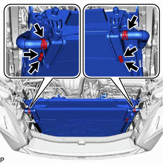
(b) Remove the 4 bolts and radiator assembly (for inverter coolant) from the cooler condenser assembly.
Installation
INSTALLATION
PROCEDURE
1. INSTALL RADIATOR ASSEMBLY (for Inverter Coolant)
| (a) Install the radiator assembly (for inverter coolant) to the cooler condenser assembly with the 4 bolts. Torque: 9.0 N·m {92 kgf·cm, 80 in·lbf} |
|
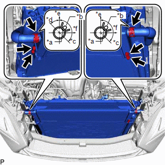
(b) Referring to the illustration, connect the No. 5 inverter cooling hose, No. 2 inverter cooling hose assembly and clamp to the radiator assembly (for inverter coolant), and secure with the hose clamp.
NOTICE:
- Until immediately before connecting the water hose, plug the water hose and pipe with vinyl tape, etc. to prevent foreign matter from entering the cooling path.
- Insert the water hose up to the tank surface of the radiator assembly (for inverter coolant).
- Align the matchmark on the water hose with the positioning rib on the radiator assembly (for inverter coolant).
2. INSTALL NO. 2 FAN SHROUD
Click here .gif)
3. INSTALL UPPER RADIATOR SUPPORT SUB-ASSEMBLY
Click here
4. ADD COOLANT (for Inverter Coolant)
Click here
5. INSPECT FOR COOLANT LEAK (for Inverter Coolant)
Click here
6. INSTALL NO. 1 ENGINE UNDER COVER ASSEMBLY
Click here
READ NEXT:
 Components
COMPONENTS ILLUSTRATION *1 HV WATER PUMP BRACKET SUB-ASSEMBLY *2 NO. 1 ENGINE UNDER COVER ASSEMBLY *3 NO. 2 INVERTER COOLING HOSE ASSEMBLY *4 WATER PUMP WITH MOTOR *5 NO. 2 I
Removal
REMOVAL PROCEDURE 1. REMOVE NO. 1 ENGINE UNDER COVER ASSEMBLY Click here 2. DRAIN COOLANT (for Inverter Coolant) Click here 3. REMOVE UPPER RADIATOR SUPPORT SUB-ASSEMBLY Click here 4. DISCONNE
SEE MORE:
Parts Location
PARTS LOCATION ILLUSTRATION *1 COMBINATION METER ASSEMBLY *2 CLIMATE CONTROL SWITCH (for Driver Side) *3 CLIMATE CONTROL SWITCH (for Front Passenger Side) *4 AIR CONDITIONING CONTROL ASSEMBLY *5 AIR CONDITIONING AMPLIFIER ASSEMBLY *6 DLC3 *7 INSTRUMENT PANEL JUNCT
Mirror Heater does not Operate with Rear Defogger Switch
DESCRIPTION When therear window defogger switch (mirror heater switch) is operated, a mirror heater signal is sent to the air conditioning amplifier assembly via LIN communication. The air conditioning amplifier assembly sends the signal to the outer mirror control ECU assembly via CAN communication
