Lexus NX: Switch Lights of Remote Touch Always Illuminate or cannot be Controlled Using Rheostat
DESCRIPTION
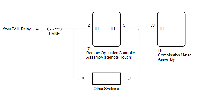
Power is supplied to the remote touch illumination when the light control switch is in the tail or head position.
HINT:
- When the remote touch is in self check mode, the switch illumination on the remote touch may remain on.
- If any illumination controlled by the rheostat switch has a malfunction such as an open circuit, the switch illumination of the remote touch is affected and cannot be controlled by the rheostat switch.
WIRING DIAGRAM
PROCEDURE
| 1. | CHECK ILLUMINATION CONTROLLED BY RHEOSTAT SWITCH |
(a) Perform the following procedure and check that the illumination controlled by the rheostat switch illuminates properly.
(1) If the vehicle is in a bright area, move it to a dark area.
HINT:
When the vehicle is in a bright area, the switch illumination may not turn on due to the auto dimmer function.
(2) If the light control switch is in the AUTO position, turn the switch to the tail or head position.
HINT:
If the light control switch is in the AUTO position, the switch illumination will not turn on unless the surrounding area is dark.
| Result | Proceed to |
|---|---|
| Any of the illumination controlled by the rheostat switch does not illuminate properly. | A |
| All of the illumination controlled by the rheostat switch illuminates properly. | B |
HINT:
The shift lever illumination and panel switch illumination are controlled by the rheostat switch. If either of these has a malfunction such as an open circuit, the switch illumination of the remote touch is affected and cannot be controlled by the rheostat switch.
| B | .gif) | GO TO STEP 3 |
|
.gif)
| 2. | REPAIR OR REPLACE ILLUMINATION CONTROLLED BY RHEOSTAT SWITCH |
(a) Repair or replace the part with the malfunctioning illumination that is controlled by the rheostat switch.
| NEXT | | GO TO STEP 3 |
| 3. | CONFIRM SYMPTOMS |
| (a) Perform the following procedure, operate the rheostat switch again, and check if illumination brightness adjustment is possible (including adjustment of other devices such as the radio receiver assembly). (1) Check if the remote touch is in self check mode. If it is, cancel self check mode. Click here HINT: When the remote touch is in self check mode, the switch illumination on the remote touch may remain on. (2) If the vehicle is in a bright area, move it to a dark area. HINT: When the vehicle is in a bright area, the switch illumination may not turn on due to the auto dimmer function. (3) If the light control switch is in the AUTO position, turn the switch to the tail or head position. HINT: If the light control switch is in the AUTO position, the switch illumination will not turn on unless the surrounding area is dark. |
|
| Result | Proceed to |
|---|---|
| Switch illumination cannot be adjusted (illumination for other devices can be adjusted). | A |
| Switch illumination cannot be adjusted (illumination for other devices also cannot be adjusted). | B |
| Switch illumination can be adjusted. | C |
| B | | GO TO METER / GAUGE SYSTEM |
| C | | END |
|
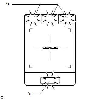
| 4. | REMOTE TOUCH SELF CHECK (SWITCH ILLUMINATION CHECK) |
(a) Enter self-diagnostic mode.
Click here .gif)
| (b) Operate the remote touch screen diagonally from the upper left to the lower right and check that the brightness of the switch illumination changes. NOTICE: Since the remote touch screen may recognize a pinch in/out or flick operation if operated with 2 fingers, always use 1 finger to operate the remote touch in self-diagnostic mode. |
|
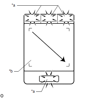
OK:
Brightness changes according to touch screen operation.
| NG | | REPLACE REMOTE OPERATION CONTROLLER ASSEMBLY (REMOTE TOUCH) |
|
| 5. | CHECK HARNESS AND CONNECTOR (ILLUMINATION SIGNAL CIRCUIT) |
| (a) Disconnect the remote operation controller assembly (remote touch) connector. |
|
.png)
(b) Measure the voltage according to the value(s) in the table below.
Standard Voltage:
| Tester Connection | Switch Condition | Specified Condition |
|---|---|---|
| I71-2 (ILL+) - Body ground | Power switch on (IG) Light control switch in tail or head position | 11 to 14 V |
| NG | | REPAIR OR REPLACE HARNESS OR CONNECTOR |
|
| 6. | CHECK HARNESS AND CONNECTOR (REMOTE OPERATION CONTROLLER ASSEMBLY [REMOTE TOUCH] - COMBINATION METER ASSEMBLY) |
(a) Disconnect the I71 remote operation controller assembly (remote touch) connector.
(b) Disconnect the I10 combination meter assembly connector.
(c) Measure the resistance according to the value(s) in the table below.
Standard Resistance:
| Tester Connection | Condition | Specified Condition |
|---|---|---|
| I71-5 (ILL-) - I10-39 (ILL-) | Always | Below 1 Ω |
| OK | | REPLACE REMOTE OPERATION CONTROLLER ASSEMBLY (REMOTE TOUCH) |
| NG | | REPAIR OR REPLACE HARNESS OR CONNECTOR |
READ NEXT:
 Switch Operation of Remote Touch not Accepted
CAUTION / NOTICE / HINT NOTICE: When replacing the radio receiver assembly, always replace it with a new one. If a radio receiver assembly which was installed to another vehicle is used, the following
Pointer Displayed/not Displayed Repeatedly
WIRING DIAGRAM CAUTION / NOTICE / HINT NOTICE:
Inspect the fuses for circuits related to this system before performing the following procedure.
When replacing the radio receiver assembly, always
Pointer not Displayed on Screen or Pointer does not Move
CAUTION / NOTICE / HINT NOTICE: When replacing the radio receiver assembly, always replace it with a new one. If a radio receiver assembly which was installed to another vehicle is used, the following
SEE MORE:
Replacement
REPLACEMENT CAUTION / NOTICE / HINT HINT: There are 2 methods for brake fluid replacement: using the Techstream or not using the Techstream. NOTICE:
Perform fluid replacement with park (P) selected and the parking brake applied.
As brake fluid may overflow when replacing brake fluid, do not pla
Components
COMPONENTS ILLUSTRATION *1 DECK FLOOR BOX LH *2 NO. 3 DECK BOARD SUB-ASSEMBLY *3 REAR DECK FLOOR BOX *4 NEGATIVE AUXILIARY BATTERY TERMINAL N*m (kgf*cm, ft.*lbf): Specified torque - - ILLUSTRATION *A for Power Tilt and Power Telescopic Steering Column *B f
