Lexus NX: System Description
SYSTEM DESCRIPTION
GENERAL
(a) Deceleration sensors used for the airbag system are installed on various parts of the vehicle and calculate the deceleration rate of each part during a collision.
(b) Depending on the situation, the airbag ECU assembly sends a deployment signal to each airbag based on the information from each sensor.
DEPLOYMENT CONDITION
(a) FRONTAL COLLISION
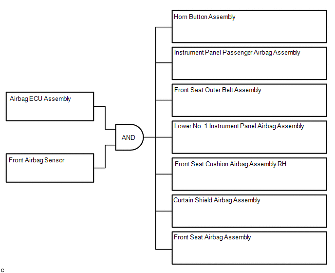
(1) Frontal collision signals are produced based on the information from the airbag ECU assembly and front airbag sensors.
HINT:
In case of a frontal collision, the SRS ignition signal could be output with the deceleration sensor ON signal even without a signal from the front airbag sensors.
(2) Frontal collision signals are used to deploy the airbags and pretensioners in the illustration.
(b) SIDE COLLISION (1)
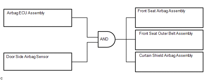
(1) Side collision (Pattern 1) signals are produced based on the information from the airbag ECU assembly and door side airbag sensor.
(2) Side collision (Pattern 1) signals are used to deploy the airbags and pretensioners in the illustration.
(c) SIDE COLLISION (2)
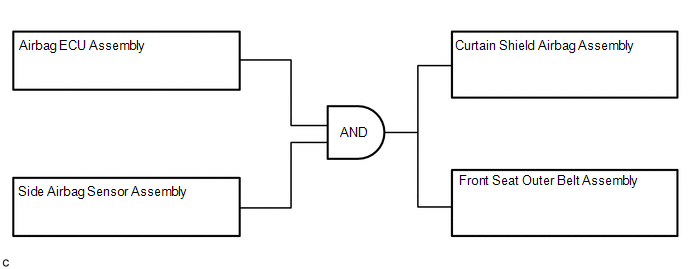
(1) Side collision (Pattern 2) signals are produced based on the information from the airbag ECU assembly and side airbag sensor assembly.
(2) Side collision (Pattern 2) signals are used to deploy the airbags and pretensioners in the illustration.
(d) ROLLOVER
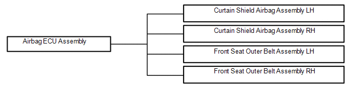
(1) A circuit to detect vehicle rollover is built into the airbag ECU assembly.
(2) When the conditions for vehicle rollover are met, the airbag ECU assembly deploys the SRS items in the illustration.
READ NEXT:
 How To Proceed With Troubleshooting
CAUTION / NOTICE / HINT HINT:
Use these procedures to troubleshoot the airbag system.
*: Use the Techstream.
PROCEDURE 1. VEHICLE BROUGHT TO WORKSHOP
NEXT 2. IN
Problem Symptoms Table
PROBLEM SYMPTOMS TABLE HINT: Use the table below to help determine the cause of problem symptoms. If multiple suspected areas are listed, the potential causes of the symptoms are listed in order of pr
Terminals Of Ecu
TERMINALS OF ECU AIRBAG ECU ASSEMBLY Terminal No. Terminal Symbol Destination I58-1 P2+ Instrument panel passenger airbag assembly (Front passenger side squib 2nd step) I58-2 P2-
SEE MORE:
Control Module Communication Bus "A" Off (U0073,U0100,U0101,U0126,U0129,U0142,U0155,U0293)
DESCRIPTION DTC No. Detection Item DTC Detection Condition Trouble Area U0073 Control Module Communication Bus "A" Off Bus off condition is detected. CAN communication system U0100 Lost Communication with ECM / PCM "A" Communication stop occurs between the headlight ECU su
Crankshaft Position Sensor "A" Circuit (P0335)
DESCRIPTION The crankshaft position sensor system consists of a crank angle sensor plate (crankshaft) and a pickup coil. The crank angle sensor plate has 34 teeth at 10° intervals (2 teeth are missing for detecting top dead center), and is installed on the crankshaft. The crankshaft position sensor
