Lexus NX: System Diagram
SYSTEM DIAGRAM
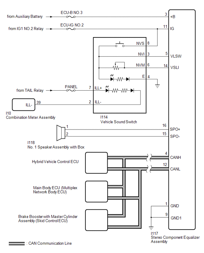 Communication Table
 | Sender | Receiver | Signal | Line |
|---|---|---|---|
| Brake booster with master cylinder assembly (skid control ECU) | Stereo component equalizer assembly | Vehicle speed signal | CAN |
| Hybrid vehicle control ECU | Stereo component equalizer assembly | Engine speed signal | |
| Accelerator pedal angle signal | |||
| Integration sports mode indicator signal | |||
| Shift position P signal | |||
| Shift position R signal | |||
| Shift position D signal | |||
| Shift position N signal | |||
| Sport mode indicator signal | |||
| Shift gear signal | |||
| Engine mode ID signal | |||
| ECO mode indicator signal | |||
| Hybrid vehicle control ECU | |||
| Integration sports mode signal | |||
| Main body ECU (multiplex network body ECU) | Stereo component equalizer assembly | Trip count signal | |
| Time count signal |
READ NEXT:
 System Description
SYSTEM DESCRIPTION ASC SYSTEM (a) The ASC system uses a stereo component equalizer assembly to electronically generate a driving sound. Simulated engine sounds are output from the No. 1 speaker assemb
How To Proceed With Troubleshooting
CAUTION / NOTICE / HINT HINT:
Use the following procedure to troubleshoot the ASC system.
*: Use the Techstream.
PROCEDURE 1. VEHICLE BROUGHT TO WORKSHOP
NEXT 2.
Operation Check
OPERATION CHECK INSPECT ASC SYSTEM OPERATION CAUTION: Check for safety before performing any tests. HINT: When the drive mode changes to a mode other than NORMAL, SPORT or CUSTOMIZE*, the simulated en
SEE MORE:
Diagnostic Trouble Code Chart
DIAGNOSTIC TROUBLE CODE CHART Sliding Roof System DTC No. Detection Item Link B2341 Sensor (Motor) Failure B2342 Switch Failure B2343 Position Initialization Incomplete B2344 Position Failure
On-vehicle Inspection
ON-VEHICLE INSPECTION CAUTION / NOTICE / HINT CAUTION: Be sure to follow the correct removal and installation procedures of the seat position airbag sensor. PROCEDURE 1. INSPECT SEAT POSITION AIRBAG SENSOR (for Vehicle not Involved in Collision) (a) Perform a diagnostic system check. Click here 2
© 2016-2024 Copyright www.lexunx.com
