Lexus NX: System Diagram
Lexus NX Service Manual / Vehicle Interior / Meter / Gauge / Display / Meter / Gauge System / System Diagram
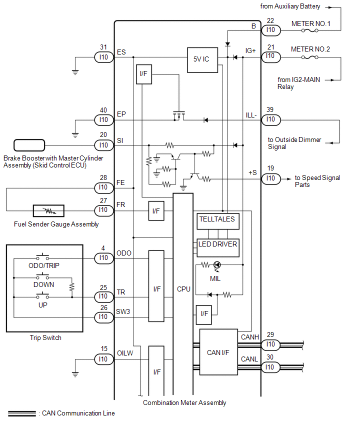
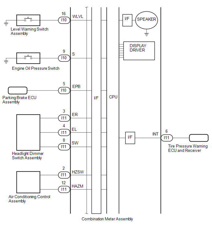
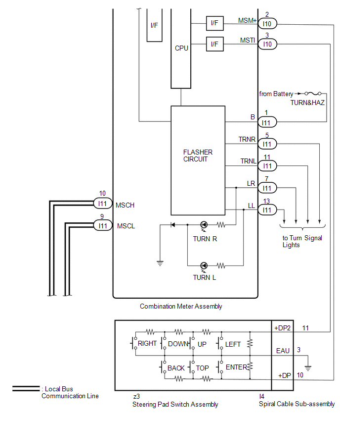
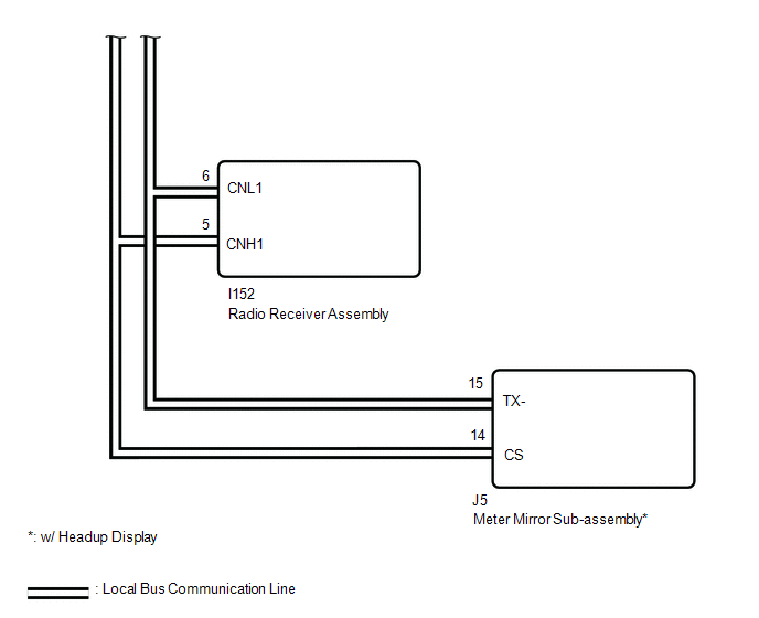
SYSTEM DIAGRAM
CAN SIGNAL
Click here .gif)
DIRECT LINE SIGNAL
READ NEXT:
 System Description
SYSTEM DESCRIPTION OUTLINE OF COMBINATION METER ASSEMBLY *a Indication Example *b Hybrid System Indicator or Tachometer *c Speedometer *d
Power Condition
ODO/TRIP Meter
How To Proceed With Troubleshooting
CAUTION / NOTICE / HINT HINT:
Use the following procedure to troubleshoot the meter / gauge system.
*: Use the Techstream.
PROCEDURE 1. VEHICLE BROUGHT TO WORKSHOP
NEXT
Operation Check
OPERATION CHECK INSPECT INDICATOR/WARNING LIGHT (a) Check the following indicators and warning lights. Indicator/Warning Light Switch Condition Specified Condition
*1: w/ Pre-collision Syst
SEE MORE:
Installation
INSTALLATION PROCEDURE 1. INSTALL NO. 4 FUEL TUBE CLAMP (a) Install the 5 No. 4 fuel tube clamps to the fuel tank assembly as shown in the illustration. 2. INSTALL FUEL TANK MAIN TUBE SUB-ASSEMBLY (a) Connect the 5 clamps and install the fuel tank main tube sub-assembly to the 5 No. 4
Yaw Rate Sensor (C1A46)
DESCRIPTION The blind spot monitor sensor receives yaw rate signals from the yaw rate sensor via CAN communication. DTC No. Detection Item DTC Detection Condition Trouble Area Note C1A46 Yaw Rate Sensor A fail flag is transmitted from the yaw rate sensor
Electronically Contro
© 2016-2024 Copyright www.lexunx.com
