- Data continuity flag
- Steering angle signal
Lexus NX: System Diagram
Lexus NX Service Manual / Audio & Visual & Telematics / Park Assist / Monitoring / Panoramic View Monitor System / System Diagram
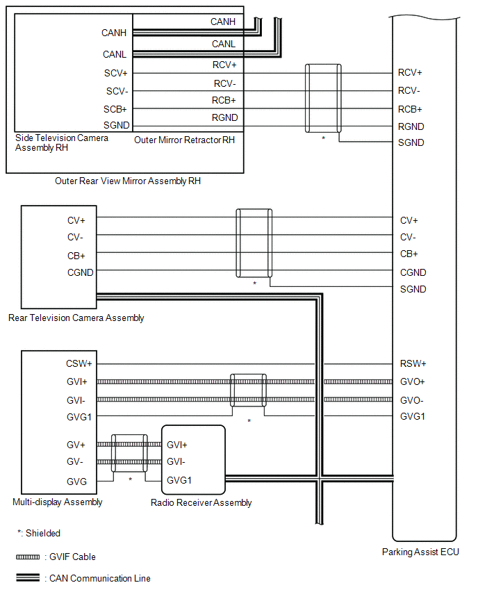
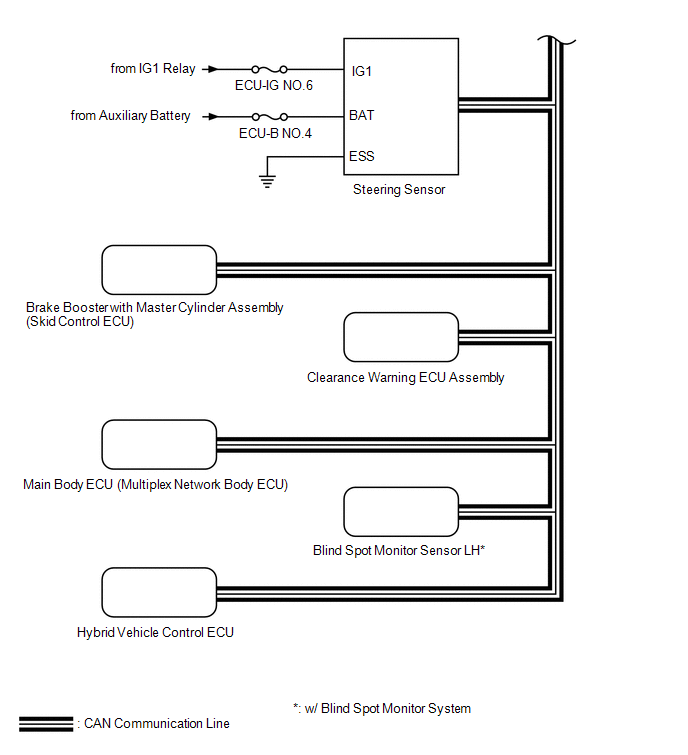
SYSTEM DIAGRAM
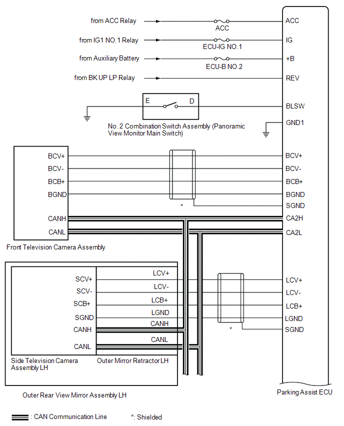
| Sender | Receiver | Signal | Line |
|---|---|---|---|
| *: w/ Blind Spot Monitor System | |||
| Parking Assist ECU | Multi-display Assembly | Display | GVIF cable |
| Radio Receiver Assembly | Multi-display Assembly | Display | GVIF cable |
| Steering Sensor | Parking Assist ECU | | CAN |
| Brake Booster with Master Cylinder Assembly (Skid Control ECU) | Parking Assist ECU |
| CAN |
| Clearance Warning ECU Assembly | Parking Assist ECU | Sensor information | CAN |
| Main Body ECU (Multiplex Network Body ECU) | Parking Assist ECU |
| CAN |
| Hybrid Vehicle Control ECU | Parking Assist ECU |
| CAN |
| Blind Spot Monitor Sensor LH* | Parking Assist ECU | RCTA information | CAN |
READ NEXT:
 System Description
SYSTEM DESCRIPTION GENERAL (a) This system has front, passenger side, driver side and rear television camera assemblies mounted around the vehicle to display around the vehicle on the multi-display as
How To Proceed With Troubleshooting
CAUTION / NOTICE / HINT HINT:
Use the following procedure to troubleshoot the panoramic view monitor system.
*: Use the Techstream.
PROCEDURE 1. VEHICLE BROUGHT TO WORKSHOP
NEXT
Initialization
INITIALIZATION INITIALIZE PANORAMIC VIEW MONITOR SYSTEM (a) When "!" mark is displayed on the multi-display assembly, correct the steering angle neutral point using the following method. (1) Fully tur
SEE MORE:
Inspection
INSPECTION PROCEDURE 1. INSPECT FRONT STABILIZER LINK ASSEMBLY LH (a) Inspect the turning torque of the ball joint. (1) Secure the front stabilizer link assembly in a vise using aluminum plates. (2) Install the nut to the front stabilizer link assembly stud. (3) Move the stud back and forth sever
Disassembly
DISASSEMBLY PROCEDURE 1. REMOVE CHILD RESTRAINT SEAT TETHER ANCHOR COVER (a) Detach the 2 claws, 2 guides and remove the child restraint seat tether anchor cover. 2. REMOVE VANITY LIGHT ASSEMBLY HINT: Use the same procedure for both vanity light assemblies.. (a) Detach the 2 claws
© 2016-2024 Copyright www.lexunx.com
