Lexus NX: Terminals Of Ecu
TERMINALS OF ECU
NOTICE:
-
After turning the power switch off, waiting time may be required before disconnecting the cable from the negative (-) auxiliary battery terminal.
Click here
.gif)
-
When disconnecting and reconnecting the auxiliary battery.
Click here
HINT:
When disconnecting and reconnecting the auxiliary battery, there is an automatic learning function that completes learning when the respective system is used.
Click here
-
Some parts must be initialized and set when replacing or removing and installing parts.
Click here
- Before measuring the resistance of the CAN bus, turn the power switch off and leave the vehicle for 1 minute or more without operating the key or any switches, or opening or closing the doors. After that, disconnect the cable from the negative (-) auxiliary battery terminal and leave the vehicle for 1 minute or more before measuring the resistance.
- This section describes the standard values for all CAN related components.
HINT:
-
The systems (ECUs and sensors) that use CAN communication vary depending on the vehicle and optional equipment. Check which systems (ECUs and sensors) are installed to the vehicle.
Click here
- Operating the power switch, any other switches or a door triggers related ECU and sensor communication on the CAN. This communication will cause the resistance value to change.
- Even after DTCs are cleared, if a DTC is stored again after driving the vehicle for a while, the malfunction may be occurring due to vibration of the vehicle. In such a case, wiggling the ECUs or wire harness while performing the inspection below may help determine the cause of the malfunction.
NO. 2 CAN JUNCTION CONNECTOR
(a) Check the No. 2 CAN junction connector.
(1) Connection diagram
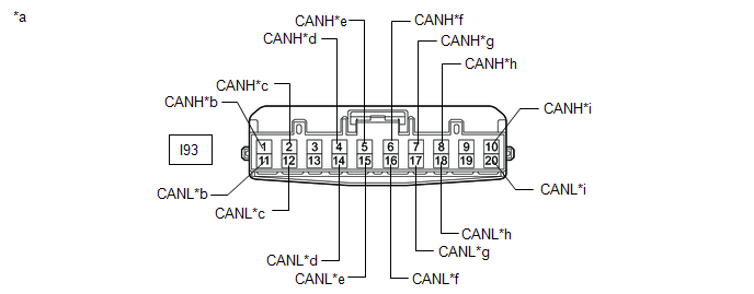
| *a | Front view of wire harness connector (to No. 2 CAN Junction Connector) | *b | for Hybrid Vehicle Control ECU |
| *c | for Stereo Component Equalizer Assembly (w/ ASC System) | *d | for Central Gateway ECU (Network Gateway ECU) |
| *e | for No. 3 CAN Junction Connector | *f | for Certification ECU (Smart Key ECU Assembly) |
| *g | for Combination Meter Assembly | *h | for Meter Mirror Sub-assembly (w/ Headup Display) |
| *i | for Airbag ECU Assembly | - | - |
(2) Check the connection diagram of the components which are connected to the No. 2 CAN junction connector.
| Terminal No. | Wiring Color | Connect to |
|---|---|---|
|
*1: w/ ASC System
*2: w/ Headup Display | ||
| I93-1 (CANH) | LG | Hybrid vehicle control ECU |
| I93-11 (CANL) | W | |
| I93-2 (CANH) | R | Stereo component equalizer assembly*1 |
| I93-12 (CANL) | W | |
| I93-4 (CANH) | B | Central gateway ECU (network gateway ECU) |
| I93-14 (CANL) | W | |
| I93-5 (CANH) | V | No. 3 CAN junction connector |
| I93-15 (CANL) | W | |
| I93-6 (CANH) | R | Certification ECU (smart key ECU assembly) |
| I93-16 (CANL) | W | |
| I93-7 (CANH) | G | Combination meter assembly |
| I93-17 (CANL) | W | |
| I93-8 (CANH) | Y | Meter mirror sub-assembly*2 |
| I93-18 (CANL) | W | |
| I93-10 (CANH) | B | Airbag ECU assembly |
| I93-20 (CANL) | W | |
NO. 3 CAN JUNCTION CONNECTOR
(a) Check the No. 3 CAN junction connector.
(1) Connection diagram
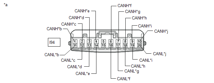
| *a | Front view of wire harness connector (to No. 3 CAN Junction Connector) | *b | for Air Conditioning Amplifier Assembly |
| *c | for Power Steering ECU Assembly | *d | for Headlight ECU Sub-assembly LH (for Triple Beam Headlight) |
| *e | for Main Body ECU (Multiplex Network Gateway ECU) | *f | for No. 2 CAN Junction Connector |
| *g | for ECM | *h | for Brake Booster with Master Cylinder Assembly (Skid Control ECU) |
| *i | for Steering Sensor | *j | for Parking Brake ECU Assembly |
(2) Check the connection diagram of the components which are connected to the No. 3 CAN junction connector.
| Terminal No. | Wiring Color | Connect to |
|---|---|---|
| *: for Triple Beam Headlight | ||
| I94-1 (CANH) | B | Air conditioning amplifier assembly |
| I94-11 (CANL) | W | |
| I94-2 (CANH) | LG | Power steering ECU assembly |
| I94-12 (CANL) | W | |
| I94-3 (CANH) | B | for Headlight ECU Sub-assembly LH* |
| I94-13 (CANL) | W | |
| I94-4 (CANH) | Y | Main body ECU (multiplex network body ECU) |
| I94-14 (CANL) | W | |
| I94-6 (CANH) | V | No. 2 CAN junction connector |
| I94-16 (CANL) | W | |
| I94-7 (CANH) | Y | ECM |
| I94-17 (CANL) | W | |
| I94-8 (CANH) | R | Brake booster with master cylinder assembly (skid control ECU) |
| I94-18 (CANL) | W | |
| I94-9 (CANH) | P | Steering sensor |
| I94-19 (CANL) | W | |
| I94-10 (CANH) | B | Parking brake ECU assembly |
| I94-20 (CANL) | W | |
NO. 4 CAN JUNCTION CONNECTOR
(a) Check the No. 4 CAN junction connector.
(1) Connection diagram
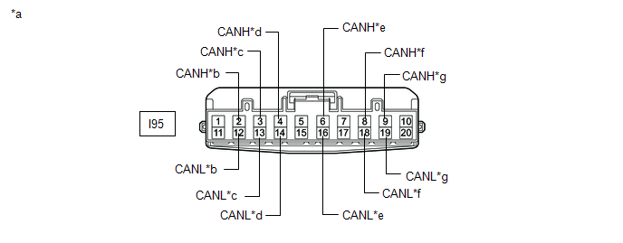
| *a | Front view of wire harness connector (to No. 4 CAN Junction Connector) | *b | for Vehicle Approaching Speaker Controller |
| *c | for Central Gateway ECU (Network Gateway ECU) | *d | for Millimeter Wave Radar Sensor Assembly (w/ Pre-collision System) |
| *e | for Clearance Warning ECU Assembly (w/ Intuitive Parking Assist System) | *f | for Forward Recognition Camera (w/ Pre-collision System) |
| *g | for No. 7 CAN Junction Connector | - | - |
(2) Check the connection diagram of the components which are connected to the No. 4 CAN junction connector.
| Terminal No. | Wiring Color | Connect to |
|---|---|---|
|
*1: w/ Pre-collision System
*2: w/ Intuitive Parking Assist System | ||
| I95-2 (CANH) | V | Vehicle approaching speaker controller |
| I95-12 (CANL) | W | |
| I95-3 (CANH) | L | Central gateway ECU (network gateway ECU) |
| I95-13 (CANL) | W | |
| I95-4 (CANH) | P | Millimeter wave radar sensor assembly*1 |
| I95-14 (CANL) | W | |
| I95-6 (CANH) | R | Clearance warning ECU assembly*2 |
| I95-16 (CANL) | W | |
| I95-8 (CANH) | B | Forward recognition camera*1 |
| I95-18 (CANL) | W | |
| I95-9 (CANH) | Y | No. 7 CAN junction connector |
| I95-19 (CANL) | W | |
NO. 5 CAN JUNCTION CONNECTOR
(a) Check the No. 5 CAN junction connector.
(1) Connection diagram
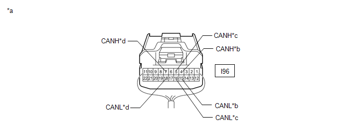
| *a | Rear view of wire harness connector (to No. 5 CAN Junction Connector) | *b | for Main Body ECU (Multiplex Network Body ECU) |
| *c | for Outer Mirror Control ECU Assembly RH (w/ Memory) | *d | for No. 6 CAN Junction Connector |
(2) Check the connection diagram of the components which are connected to the No. 5 CAN junction connector.
| Terminal No. | Wiring Color | Connect to |
|---|---|---|
| *: w/ Memory | ||
| I96-4 (CANH) | B | Main body ECU (multiplex network body ECU) |
| I96-15 (CANL) | W | |
| I96-5 (CANH) | R | Outer mirror control ECU assembly RH* |
| I96-16 (CANL) | W | |
| I96-7 (CANH) | V | No. 6 CAN junction connector |
| I96-18 (CANL) | W | |
NO. 6 CAN JUNCTION CONNECTOR
(a) Check the No. 6 CAN junction connector.
(1) Connection diagram
| *a | Rear view of wire harness connector (to No. 6 CAN Junction Connector) | *b | for Multiplex Tilt and Telescopic ECU (for Power Tilt and Power Telescopic Steering Column) |
| *c | for No. 8 CAN Junction Connector | *d | for No. 5 CAN Junction Connector |
| *e | for Front Power Seat Switch (for Driver Side) (w/ Memory) | *f | for Outer Mirror Control ECU Assembly LH (w/ Memory) |
(2) Check the connection diagram of the components which are connected to the No. 6 CAN junction connector.
| Terminal No. | Wiring Color | Connect to |
|---|---|---|
|
*1: for Power Tilt and Power Telescopic Steering Column
*2: w/ Memory | ||
| I97-4 (CANH) | G | Multiplex tilt and telescopic ECU*1 |
| I97-15 (CANL) | W | |
| I97-5 (CANH) | L | No. 8 CAN junction connector |
| I97-16 (CANL) | W | |
| I97-6 (CANH) | V | No. 5 CAN junction connector |
| I97-17 (CANL) | W | |
| I97-7 (CANH) | G | Front power seat switch (for driver side)*2 |
| I97-18 (CANL) | W | |
| I97-8 (CANH) | B | Outer mirror control ECU assembly LH*2 |
| I97-19 (CANL) | W | |
NO. 7 CAN JUNCTION CONNECTOR
(a) Check the No. 7 CAN junction connector.
(1) Connection diagram
| *a | Front view of wire harness connector (to No. 7 CAN Junction Connector) | *b | for Parking Assist ECU (w/ Panoramic View Monitor System) |
| *c | for Blind Spot Monitor Sensor LH (w/ Blind Spot Monitor System) | *d | for Central Gateway ECU (Network Gateway ECU) |
| *e | for No. 4 CAN Junction Connector | *f | for Absorber Control ECU (w/ Adaptive Variable Suspension System) |
| *g | for Rear Television Camera Assembly | - | - |
(2) Check the connection diagram of the components which are connected to the No. 7 CAN junction connector.
| Terminal No. | Wiring Color | Connect to |
|---|---|---|
|
*1: w/ Panoramic View Monitor System
*2: w/ Blind Spot Monitor System *3: w/ Adaptive Variable Suspension System | ||
| Q32-2 (CANH) | G | Parking assist ECU*1 |
| Q32-12 (CANL) | W | |
| Q32-3 (CANH) | R | Blind spot monitor sensor LH*2 |
| Q32-13 (CANL) | W | |
| Q32-4 (CANH) | P | Central gateway ECU (network gateway ECU) |
| Q32-14 (CANL) | W | |
| Q32-5 (CANH) | L | No. 4 CAN junction connector |
| Q32-15 (CANL) | W | |
| Q32-7 (CANH) | B | Absorber control ECU*3 |
| Q32-17 (CANL) | W | |
| Q32-8 (CANH) | Y | Rear television camera assembly |
| Q32-18 (CANL) | P | |
NO. 8 CAN JUNCTION CONNECTOR
(a) Check the No. 8 CAN junction connector.
(1) Connection diagram
| *a | Rear view of wire harness connector (to No. 8 CAN Junction Connector) | *b | for No. 6 CAN Junction Connector |
| *c | for Multiplex Network Door ECU (w/ Power Back Door System) | *d | for No. 2 CAN Junction Terminal |
(2) Check the connection diagram of the components which are connected to the No. 8 CAN junction connector.
| Terminal No. | Wiring Color | Connect to |
|---|---|---|
| *: w/ Power Back Door System | ||
| Y22-5 (CANH) | G | No. 6 CAN junction connector |
| Y22-16 (CANL) | W | |
| Y22-6 (CANH) | G | Multiplex network door ECU* |
| Y22-17 (CANL) | W | |
| Y22-7 (CANH) | G | No. 2 CAN junction terminal |
| Y22-18 (CANL) | W | |
NO. 10 CAN JUNCTION CONNECTOR
(a) Check the No. 10 CAN junction connector.
(1) Connection diagram
| *a | Front view of wire harness connector (to No. 10 CAN Junction Connector) | *b | for Central Gateway ECU (Network Gateway ECU) |
| *c | for Radio Receiver Assembly | *d | for DCM (Telematics Transceiver) (w/ Telematics Transceiver) |
| *e | for Bus Buffer ECU (w/ Bus Buffer ECU) | *f | for Central Gateway ECU (Network Gateway ECU) |
(2) Check the connection diagram of the components which are connected to the No. 10 CAN junction connector.
| Terminal No. | Wiring Color | Connect to |
|---|---|---|
|
*1: w/ Telematics Transceiver
*2: w/ Bus Buffer ECU | ||
| I164-1 (CANH) | R | Central gateway ECU (network gateway ECU) |
| I164-12 (CANL) | W | |
| I164-2 (CANH) | B | Radio receiver assembly |
| I164-13 (CANL) | W | |
| I164-3 (CANH) | Y | DCM (Telematics transceiver)*1 |
| I164-14 (CANL) | W | |
| I164-4 (CANH) | LG | Bus buffer ECU*2 |
| I164-15 (CANL) | W | |
| I164-5 (CANH) | L | Central gateway ECU (network gateway ECU) |
| I164-16 (CANL) | W | |
NO. 2 CAN JUNCTION TERMINAL
(a) Check the No. 2 CAN junction terminal connector.
(1) Connection diagram
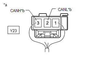
| *a | Rear view of wire harness connector (to No. 2 CAN Junction Terminal) |
| *b | for No. 8 CAN Junction Connector |
(2) Check the connection diagram of the components which are connected to the No. 2 CAN junction terminal connector.
| Terminal No. | Wiring Color | Connect to |
|---|---|---|
| Y23-2 (CANL) | W | No. 8 CAN junction connector |
| Y23-3 (CANH) | G |
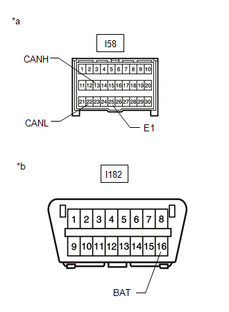
DLC3
(a) Disconnect the cable from the negative (-) auxiliary battery terminal before measuring the resistances of the CAN main wire and CAN branch wire.
CAUTION:
Wait at least 90 seconds after disconnecting the cable from the negative (-) auxiliary battery terminal to disable the SRS system.
NOTICE:
After turning the power switch off, waiting time may be required before disconnecting the cable from the negative (-) auxiliary battery terminal. Therefore, make sure to read the disconnecting the cable from the negative (-) auxiliary battery terminal notice before proceeding with work.
Click here
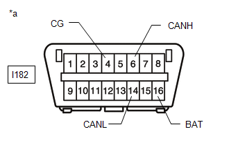
| *a | Front view of DLC3 |
(b) Measure the resistance according to the value(s) in the table below.
| Terminal No. (Symbol) | Wiring Color | Terminal Description | Condition | Specified Condition |
|---|---|---|---|---|
| I182-6 (CANH) - I182-14 (CANL) | B - W | HIGH-level CAN bus line - LOW-level CAN bus line | Cable disconnected from negative (-) auxiliary battery terminal | 54 to 69 Ω |
| I182-6 (CANH) - I182-4 (CG) | B - W-B | HIGH-level CAN bus line - GND | Cable disconnected from negative (-) auxiliary battery terminal | 200 Ω or higher |
| I182-14 (CANL) - I182-4 (CG) | W - W-B | LOW-level CAN bus line - GND | Cable disconnected from negative (-) auxiliary battery terminal | 200 Ω or higher |
| I182-6 (CANH) - I182-16 (BAT) | B - L | HIGH-level CAN bus line - Auxiliary battery positive (+) | Cable disconnected from negative (-) auxiliary battery terminal | 6 kΩ or higher |
| I182-14 (CANL) - I182-16 (BAT) | W - L | LOW-level CAN bus line - Auxiliary battery positive (+) | Cable disconnected from negative (-) auxiliary battery terminal | 6 kΩ or higher |
CENTRAL GATEWAY ECU (NETWORK GATEWAY ECU)
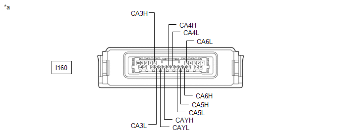
| *a | Component without harness connected (Central Gateway ECU [Network Gateway ECU]) | - | - |
(a) Disconnect the cable from the negative (-) auxiliary battery terminal.
(b) Disconnect the central gateway ECU (network gateway ECU) connector.
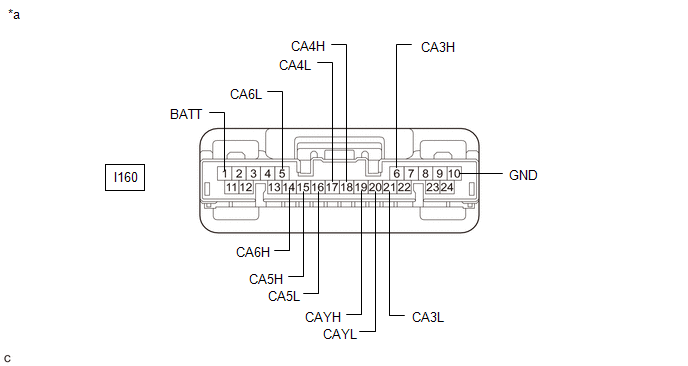
| *a | Front view of wire harness connector (to Central Gateway ECU [Network Gateway ECU]) | - | - |
(c) Measure the resistance according to the value(s) in the table below.
Standard Resistance:
V Bus Branch Lines (DLC3 - Central Gateway ECU [Network Gateway ECU])| Terminal No. (Symbol) | Wiring Color | Terminal Description | Condition | Specified Condition |
|---|---|---|---|---|
| I160-14 (CA6H) - I160-5 (CA6L) | B - W | HIGH-level CAN bus line - LOW-level CAN bus line | Cable disconnected from negative (-) auxiliary battery terminal | 1 MΩ or higher |
| I160-14 (CA6H) - I160-10 (GND) | B - W-B | HIGH-level CAN bus line - Ground | Cable disconnected from negative (-) auxiliary battery terminal | 200 Ω or higher |
| I160-5 (CA6L) - I160-10 (GND) | W - W-B | LOW-level CAN bus line - Ground | Cable disconnected from negative (-) auxiliary battery terminal | 200 Ω or higher |
| I160-14 (CA6H) - I160-1 (BATT) | B - LG | HIGH-level CAN bus line - Auxiliary battery positive (+) | Cable disconnected from negative (-) auxiliary battery terminal | 6 kΩ or higher |
| I160-5 (CA6L) - I160-1 (BATT) | W - LG | LOW-level CAN bus line - Auxiliary battery positive (+) | Cable disconnected from negative (-) auxiliary battery terminal | 6 kΩ or higher |
| Terminal No. (Symbol) | Wiring Color | Terminal Description | Condition | Specified Condition |
|---|---|---|---|---|
| I160-18 (CA4H) - I160-17 (CA4L) | B - W | HIGH-level CAN bus line - LOW-level CAN bus line | Cable disconnected from negative (-) auxiliary battery terminal | 54 to 69 Ω |
| I160-18 (CA4H) - I160-10 (GND) | B - W-B | HIGH-level CAN bus line - Ground | Cable disconnected from negative (-) auxiliary battery terminal | 200 Ω or higher |
| I160-17 (CA4L) - I160-10 (GND) | W - W-B | LOW-level CAN bus line - Ground | Cable disconnected from negative (-) auxiliary battery terminal | 200 Ω or higher |
| I160-18 (CA4H) - I160-1 (BATT) | B - LG | HIGH-level CAN bus line - Auxiliary battery positive (+) | Cable disconnected from negative (-) auxiliary battery terminal | 6 kΩ or higher |
| I160-17 (CA4L) - I160-1 (BATT) | W - LG | LOW-level CAN bus line - Auxiliary battery positive (+) | Cable disconnected from negative (-) auxiliary battery terminal | 6 kΩ or higher |
| Terminal No. (Symbol) | Wiring Color | Terminal Description | Condition | Specified Condition |
|---|---|---|---|---|
| I160-6 (CA3H) - I160-21 (CA3L) | R - W | HIGH-level CAN bus line - LOW-level CAN bus line | Cable disconnected from negative (-) auxiliary battery terminal | 1 MΩ or higher |
| I160-6 (CA3H) - I160-19 (CAYH) | R - L | HIGH-level CAN bus line - HIGH-level CAN bus line | Cable disconnected from negative (-) auxiliary battery terminal | Below 1 Ω |
| I160-21 (CA3L) - I160-20 (CAYL) | W - W | LOW-level CAN bus line - LOW-level CAN bus line | Cable disconnected from negative (-) auxiliary battery terminal | Below 1 Ω |
| I160-6 (CA3H) - I160-10 (GND) | R - W-B | HIGH-level CAN bus line - Ground | Cable disconnected from negative (-) auxiliary battery terminal | 200 Ω or higher |
| I160-21 (CA3L) - I160-10 (GND) | W - W-B | LOW-level CAN bus line - Ground | Cable disconnected from negative (-) auxiliary battery terminal | 200 Ω or higher |
| I160-6 (CA3H) - I160-1 (BATT) | R - LG | HIGH-level CAN bus line - Auxiliary battery positive (+) | Cable disconnected from negative (-) auxiliary battery terminal | 6 kΩ or higher |
| I160-21 (CA3L) - I160-1 (BATT) | W - LG | LOW-level CAN bus line - Auxiliary battery positive (+) | Cable disconnected from negative (-) auxiliary battery terminal | 6 kΩ or higher |
| Terminal No. (Symbol) | Wiring Color | Terminal Description | Condition | Specified Condition |
|---|---|---|---|---|
| I160-15 (CA5H) - I160-16 (CA5L) | L - W | HIGH-level CAN bus line - LOW-level CAN bus line | Cable disconnected from negative (-) auxiliary battery terminal | 108 to 132 Ω |
| I160-15 (CA5H) - I160-10 (GND) | L - W-B | HIGH-level CAN bus line - Ground | Cable disconnected from negative (-) auxiliary battery terminal | 200 Ω or higher |
| I160-16 (CA5L) - I160-10 (GND) | W - W-B | LOW-level CAN bus line - Ground | Cable disconnected from negative (-) auxiliary battery terminal | 200 Ω or higher |
| I160-15 (CA5H) - I160-1 (BATT) | L - LG | HIGH-level CAN bus line - Auxiliary battery positive (+) | Cable disconnected from negative (-) auxiliary battery terminal | 6 kΩ or higher |
| I160-16 (CA5L) - I160-1 (BATT) | W - LG | LOW-level CAN bus line - Auxiliary battery positive (+) | Cable disconnected from negative (-) auxiliary battery terminal | 6 kΩ or higher |
ECM
Refer to Terminals of ECU.
Click here
(a) Disconnect the cable from the negative (-) auxiliary battery terminal.
(b) Disconnect the ECM connectors.
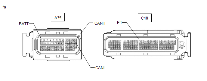
| *a | Front view of wire harness connector (to ECM) | - | - |
(c) Measure the resistance according to the value(s) in the table below.
Standard Resistance:
| Terminal No. (Symbol) | Wiring Color | Terminal Description | Condition | Specified Condition |
|---|---|---|---|---|
| A35-13 (CANH) - A35-26 (CANL) | Y - W | HIGH-level CAN bus line - LOW-level CAN bus line | Cable disconnected from negative (-) auxiliary battery terminal | 108 to 132 Ω |
| A35-13 (CANH) - C48-16 (E1) | Y - BR | HIGH-level CAN bus line - GND | Cable disconnected from negative (-) auxiliary battery terminal | 200 Ω or higher |
| A35-26 (CANL) - C48-16 (E1) | W - BR | LOW-level CAN bus line - GND | Cable disconnected from negative (-) auxiliary battery terminal | 200 Ω or higher |
| A35-13 (CANH) - A35-1 (BATT) | Y - V | HIGH-level CAN bus line - Auxiliary battery positive (+) | Cable disconnected from negative (-) auxiliary battery terminal | 6 kΩ or higher |
| A35-26 (CANL) - A35-1 (BATT) | W - V | LOW-level CAN bus line - Auxiliary battery positive (+) | Cable disconnected from negative (-) auxiliary battery terminal | 6 kΩ or higher |
CHECK HYBRID VEHICLE CONTROL ECU
Refer to Terminals of ECU.
Click here
(a) Disconnect the cable from the negative (-) auxiliary battery terminal.
(b) Disconnect the hybrid vehicle control ECU connectors.
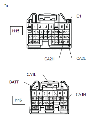
| *a | Front view of wire harness connector (to Hybrid Vehicle Control ECU) |
(c) Measure the resistance according to the value(s) in the table below.
Standard Resistance:
Bus 2 Branch Lines| Terminal No. (Symbol) | Wiring Color | Terminal Description | Condition | Specified Condition |
|---|---|---|---|---|
| I115-34 (CA2H) - I115-35 (CA2L) | P - W | HIGH-level CAN bus line - LOW-level CAN bus line | Cable disconnected from negative (-) auxiliary battery terminal | 54 to 69 Ω |
| I115-34 (CA2H) - I116-6 (E1) | P - W-B | HIGH-level CAN bus line - GND | Cable disconnected from negative (-) auxiliary battery terminal | 200 Ω or higher |
| I115-35 (CA2L) - I116-6 (E1) | W - W-B | LOW-level CAN bus line - GND | Cable disconnected from negative (-) auxiliary battery terminal | 200 Ω or higher |
| I115-34 (CA2H) - I116-3 (BATT) | P - R | HIGH-level CAN bus line - Auxiliary battery positive (+) | Cable disconnected from negative (-) auxiliary battery terminal | 6 kΩ or higher |
| I115-35 (CA2L) - I116-3 (BATT) | W - R | LOW-level CAN bus line - Auxiliary battery positive (+) | Cable disconnected from negative (-) auxiliary battery terminal | 6 kΩ or higher |
| Terminal No. (Symbol) | Wiring Color | Terminal Description | Condition | Specified Condition |
|---|---|---|---|---|
| I116-25 (CA1H) - I116-24 (CA1L) | LG - W | HIGH-level CAN bus line - LOW-level CAN bus line | Cable disconnected from negative (-) auxiliary battery terminal | 108 to 132 Ω |
| I116-25 (CA1H) - I116-6 (E1) | LG - W-B | HIGH-level CAN bus line - GND | Cable disconnected from negative (-) auxiliary battery terminal | 200 Ω or higher |
| I116-234 (CA1L) - I116-6 (E1) | W - W-B | LOW-level CAN bus line - GND | Cable disconnected from negative (-) auxiliary battery terminal | 200 Ω or higher |
| I116-25 (CA1H) - I116-3 (BATT) | LG - R | HIGH-level CAN bus line - Auxiliary battery positive (+) | Cable disconnected from negative (-) auxiliary battery terminal | 6 kΩ or higher |
| I116-24 (CA1L) - I116-3 (BATT) | W - R | LOW-level CAN bus line - Auxiliary battery positive (+) | Cable disconnected from negative (-) auxiliary battery terminal | 6 kΩ or higher |
MAIN BODY ECU (MULTIPLEX NETWORK BODY ECU)
Refer to Terminals of ECU.
Click here
(a) Disconnect the cable from the negative (-) auxiliary battery terminal.
(b) Disconnect the main body ECU (multiplex network body ECU) connectors.
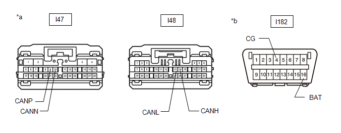
| *a | Front view of wire harness connector (to Main Body ECU [Multiplex Network Body ECU]) | *b | Front view of DLC3 |
(c) Measure the resistance according to the value(s) in the table below.
Standard Resistance:
Bus 2 Branch Lines| Terminal No. (Symbol) | Wiring Color | Terminal Description | Condition | Specified Condition |
|---|---|---|---|---|
| I48-14 (CANH) - I48-13 (CANL) | Y - W | HIGH-level CAN bus line - LOW-level CAN bus line | Cable disconnected from negative (-) auxiliary battery terminal | 54 to 69 Ω |
| I48-14 (CANH) - I182-4 (CG) | Y - W-B | HIGH-level CAN bus line - Ground | Cable disconnected from negative (-) auxiliary battery terminal | 200 Ω or higher |
| I48-13 (CANL) - I182-4 (CG) | W - W-B | LOW-level CAN bus line - Ground | Cable disconnected from negative (-) auxiliary battery terminal | 200 Ω or higher |
| I48-14 (CANH) - I182-16 (BAT) | Y - L | HIGH-level CAN bus line - Auxiliary battery positive (+) | Cable disconnected from negative (-) auxiliary battery terminal | 6 kΩ or higher |
| I48-13 (CANL) - I182-16 (BAT) | W - L | LOW-level CAN bus line - Auxiliary battery positive (+) | Cable disconnected from negative (-) auxiliary battery terminal | 6 kΩ or higher |
| Terminal No. (Symbol) | Wiring Color | Terminal Description | Condition | Specified Condition |
|---|---|---|---|---|
| I47-9 (CANP) - I47-10 (CANN) | B - W | HIGH-level CAN bus line - LOW-level CAN bus line | Cable disconnected from negative (-) auxiliary battery terminal | 108 to 132 Ω |
| I47-9 (CANP) - I182-4 (CG) | B - W-B | HIGH-level CAN bus line - Ground | Cable disconnected from negative (-) auxiliary battery terminal | 200 Ω or higher |
| I47-10 (CANN) - I182-4 (CG) | W - W-B | LOW-level CAN bus line - Ground | Cable disconnected from negative (-) auxiliary battery terminal | 200 Ω or higher |
| I47-9 (CANP) - I182-16 (BAT) | B - L | HIGH-level CAN bus line - Auxiliary battery positive (+) | Cable disconnected from negative (-) auxiliary battery terminal | 6 kΩ or higher |
| I47-10 (CANN) - I182-16 (BAT) | W - L | LOW-level CAN bus line - Auxiliary battery positive (+) | Cable disconnected from negative (-) auxiliary battery terminal | 6 kΩ or higher |
CERTIFICATION ECU (SMART KEY ECU ASSEMBLY)
Refer to Terminals of ECU.
Click here
(a) Disconnect the cable from the negative (-) auxiliary battery terminal.
(b) Disconnect the certification ECU (smart key ECU assembly) connector.
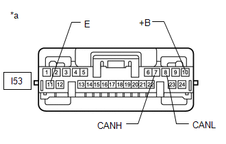
| *a | Front view of wire harness connector (to Certification ECU [Smart Key ECU Assembly]) |
(c) Measure the resistance according to the value(s) in the table below.
Standard Resistance:
| Terminal No. (Symbol) | Wiring Color | Terminal Description | Condition | Specified Condition |
|---|---|---|---|---|
| I53-7 (CANH) - I53-8 (CANL) | R - W | HIGH-level CAN bus line - LOW-level CAN bus line | Cable disconnected from negative (-) auxiliary battery terminal | 54 to 69 Ω |
| I53-7 (CANH) - I53-11 (E) | R - W-B | HIGH-level CAN bus line - GND | Cable disconnected from negative (-) auxiliary battery terminal | 200 Ω or higher |
| I53-8 (CANL) - I53-11 (E) | W - W-B | LOW-level CAN bus line - GND | Cable disconnected from negative (-) auxiliary battery terminal | 200 Ω or higher |
| I53-7 (CANH) - I53-10 (+B) | R - W | HIGH-level CAN bus line - Auxiliary battery positive (+) | Cable disconnected from negative (-) auxiliary battery terminal | 6 kΩ or higher |
| I53-8 (CANL) - I53-10 (+B) | W - W | LOW-level CAN bus line - Auxiliary battery positive (+) | Cable disconnected from negative (-) auxiliary battery terminal | 6 kΩ or higher |
POWER STEERING ECU ASSEMBLY (for Power Tilt and Power Telescopic Steering Column)
Refer to Terminals of ECU.
Click here
(a) Disconnect the cable from the negative (-) auxiliary battery terminal.
(b) Disconnect the power steering ECU assembly connectors.
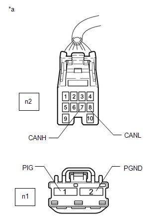
| *a | Front view of wire harness connector (to Power Steering ECU Assembly) |
(c) Measure the resistance according to the value(s) in the table below.
Standard Resistance:
| Terminal No. (Symbol) | Wiring Color | Terminal Description | Condition | Specified Condition |
|---|---|---|---|---|
| n2-7 (CANH) - n2-8 (CANL) | W - B | HIGH-level CAN bus line - LOW-level CAN bus line | Cable disconnected from negative (-) auxiliary battery terminal | 54 to 69 Ω |
| n2-7 (CANH) - n1-2 (PGND) | W - B | HIGH-level CAN bus line - GND | Cable disconnected from negative (-) auxiliary battery terminal | 200 Ω or higher |
| n2-8 (CANL) - n1-2 (PGND) | B - B | LOW-level CAN bus line - GND | Cable disconnected from negative (-) auxiliary battery terminal | 200 Ω or higher |
| n2-7 (CANH) - n1-1 (PIG) | W - R | HIGH-level CAN bus line - Auxiliary battery positive (+) | Cable disconnected from negative (-) auxiliary battery terminal | 6 kΩ or higher |
| n2-8 (CANL) - n1-1 (PIG) | B - R | LOW-level CAN bus line - Auxiliary battery positive (+) | Cable disconnected from negative (-) auxiliary battery terminal | 6 kΩ or higher |
POWER STEERING ECU ASSEMBLY (for Manual Tilt and Manual Telescopic Steering Column)
Refer to Terminals of ECU.
Click here
(a) Disconnect the cable from the negative (-) auxiliary battery terminal.
(b) Disconnect the power steering ECU assembly connectors.
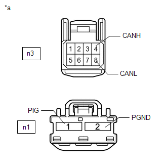
| *a | Front view of wire harness connector (to Power Steering ECU Assembly) |
(c) Measure the resistance according to the value(s) in the table below.
Standard Resistance:
| Terminal No. (Symbol) | Wiring Color | Terminal Description | Condition | Specified Condition |
|---|---|---|---|---|
| n3-4 (CANH) - n3-8 (CANL) | W - B | HIGH-level CAN bus line - LOW-level CAN bus line | Cable disconnected from negative (-) auxiliary battery terminal | 54 to 69 Ω |
| n3-4 (CANH) - n1-2 (PGND) | W - B | HIGH-level CAN bus line - GND | Cable disconnected from negative (-) auxiliary battery terminal | 200 Ω or higher |
| n3-8 (CANL) - n1-2 (PGND) | B - B | LOW-level CAN bus line - GND | Cable disconnected from negative (-) auxiliary battery terminal | 200 Ω or higher |
| n3-4 (CANH) - n1-1 (PIG) | W - R | HIGH-level CAN bus line - Auxiliary battery positive (+) | Cable disconnected from negative (-) auxiliary battery terminal | 6 kΩ or higher |
| n3-8 (CANL) - n1-1 (PIG) | B - R | LOW-level CAN bus line - Auxiliary battery positive (+) | Cable disconnected from negative (-) auxiliary battery terminal | 6 kΩ or higher |
BRAKE BOOSTER WITH MASTER CYLINDER ASSEMBLY (SKID CONTROL ECU)
Refer to Terminals of ECU.
Click here
(a) Disconnect the cable from the negative (-) auxiliary battery terminal.
(b) Disconnect the brake booster with master cylinder assembly (skid control ECU) connector.
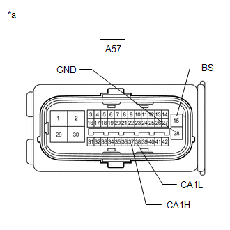
| *a | Front view of wire harness connector (to Brake Booster with Master Cylinder Assembly [Skid Control ECU]) |
(c) Measure the resistance according to the value(s) in the table below.
Standard Resistance:
| Terminal No. (Symbol) | Wiring Color | Terminal Description | Condition | Specified Condition |
|---|---|---|---|---|
| A57-37 (CA1H) - A57-38 (CA1L) | R - W | HIGH-level CAN bus line - LOW-level CAN bus line | Cable disconnected from negative (-) auxiliary battery terminal | 54 to 69 Ω |
| A57-37 (CA1H) - A57-28 (GND) | R - W-B | HIGH-level CAN bus line - GND | Cable disconnected from negative (-) auxiliary battery terminal | 200 Ω or higher |
| A57-38 (CA1L) - A57-28 (GND) | W - W-B | LOW-level CAN bus line - GND | Cable disconnected from negative (-) auxiliary battery terminal | 200 Ω or higher |
| A57-37 (CA1H) - A57-15 (BS) | R - B | HIGH-level CAN bus line - Auxiliary battery positive (+) | Cable disconnected from negative (-) auxiliary battery terminal | 6 kΩ or higher |
| A57-38 (CA1L) - A57-15 (BS) | W - B | LOW-level CAN bus line - Auxiliary battery positive (+) | Cable disconnected from negative (-) auxiliary battery terminal | 6 kΩ or higher |
AIRBAG ECU ASSEMBLY
Refer to Terminals of ECU.
Click here
(a) Disconnect the cable from the negative (-) auxiliary battery terminal, and wait for at least 90 seconds.
(b) Disconnect the airbag ECU assembly connector.
Click here
| *a | Front view of wire harness connector (to Airbag ECU Assembly) |
| *b | Front view of DLC3 |
(c) Measure the resistance according to the value(s) in the table below.
Standard Resistance:
| Terminal No. (Symbol) | Wiring Color | Terminal Description | Condition | Specified Condition |
|---|---|---|---|---|
| I58-13 (CANH) - I58-22 (CANL) | B - W | HIGH-level CAN bus line - LOW-level CAN bus line | Cable disconnected from negative (-) auxiliary battery terminal | 54 to 69 Ω |
| I58-13 (CANH) - I58-25 (E1) | B - W-B | HIGH-level CAN bus line - GND | Cable disconnected from negative (-) auxiliary battery terminal | 200 Ω or higher |
| I58-22 (CANL) - I58-25 (E1) | W - W-B | LOW-level CAN bus line - GND | Cable disconnected from negative (-) auxiliary battery terminal | 200 Ω or higher |
| I58-13 (CANH) - I182-16 (BAT) | B - L | HIGH-level CAN bus line - Auxiliary battery positive (+) | Cable disconnected from negative (-) auxiliary battery terminal | 6 kΩ or higher |
| I58-22 (CANL) - I182-16 (BAT) | W - L | LOW-level CAN bus line - Auxiliary battery positive (+) | Cable disconnected from negative (-) auxiliary battery terminal | 6 kΩ or higher |
STEERING SENSOR
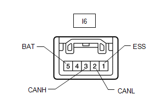
(a) Disconnect the cable from the negative (-) auxiliary battery terminal.
(b) Disconnect the steering sensor connector.
| *a | Front view of wire harness connector (to Steering Sensor) |
(c) Measure the resistance according to the value(s) in the table below.
Standard Resistance:
| Terminal No. (Symbol) | Wiring Color | Terminal Description | Condition | Specified Condition |
|---|---|---|---|---|
| I6-3 (CANH) - I6-2 (CANL) | P - W | HIGH-level CAN bus line - LOW-level CAN bus line | Cable disconnected from negative (-) auxiliary battery terminal | 54 to 69 Ω |
| I6-3 (CANH) - I6-1 (ESS) | P - W-B | HIGH-level CAN bus line - GND | Cable disconnected from negative (-) auxiliary battery terminal | 200 Ω or higher |
| I6-2 (CANL) - I6-1 (ESS) | W - W-B | LOW-level CAN bus line - GND | Cable disconnected from negative (-) auxiliary battery terminal | 200 Ω or higher |
| I6-3 (CANH) - I6-5 (BAT) | P - SB | HIGH-level CAN bus line - Auxiliary battery positive (+) | Cable disconnected from negative (-) auxiliary battery terminal | 6 kΩ or higher |
| I6-2 (CANL) - I6-5 (BAT) | W - SB | LOW-level CAN bus line - Auxiliary battery positive (+) | Cable disconnected from negative (-) auxiliary battery terminal | 6 kΩ or higher |
AIR CONDITIONING AMPLIFIER ASSEMBLY
Refer to Terminals of ECU.
Click here
(a) Disconnect the cable from the negative (-) auxiliary battery terminal.
(b) Disconnect the air conditioning amplifier assembly connector.
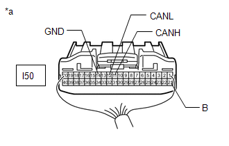
| *a | Rear view of wire harness connector (to Air Conditioning Amplifier Assembly) |
(c) Measure the resistance according to the value(s) in the table below.
Standard Resistance:
| Terminal No. (Symbol) | Wiring Color | Terminal Description | Condition | Specified Condition |
|---|---|---|---|---|
| I50-11 (CANH) - I50-12 (CANL) | B - W | HIGH-level CAN bus line - LOW-level CAN bus line | Cable disconnected from negative (-) auxiliary battery terminal | 54 to 69 Ω |
| I50-11 (CANH) - I50-14 (GND) | B - W-B | HIGH-level CAN bus line - GND | Cable disconnected from negative (-) auxiliary battery terminal | 200 Ω or higher |
| I50-12 (CANL) - I50-14 (GND) | W - W-B | LOW-level CAN bus line - GND | Cable disconnected from negative (-) auxiliary battery terminal | 200 Ω or higher |
| I50-11 (CANH) - I50-21 (B) | B - GR | HIGH-level CAN bus line - Auxiliary battery positive (+) | Cable disconnected from negative (-) auxiliary battery terminal | 6 kΩ or higher |
| I50-12 (CANL) - I50-21 (B) | W - GR | LOW-level CAN bus line - Auxiliary battery positive (+) | Cable disconnected from negative (-) auxiliary battery terminal | 6 kΩ or higher |
RADIO RECEIVER ASSEMBLY
Refer to Terminals of ECU.
Click here
(a) Disconnect the cable from the negative (-) auxiliary battery terminal.
(b) Disconnect the radio receiver assembly connectors.
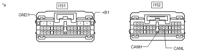
| *a | Front view of wire harness connector (to Radio Receiver Assembly) | - | - |
(c) Measure the resistance according to the value(s) in the table below.
Standard Resistance:
| Terminal No. (Symbol) | Wiring Color | Terminal Description | Condition | Specified Condition |
|---|---|---|---|---|
| I152-13 (CANH) - I152-14 (CANL) | B - W | HIGH-level CAN bus line - LOW-level CAN bus line | Cable disconnected from negative (-) auxiliary battery terminal | 54 to 69 Ω |
| I152-13 (CANH) - I151-1 (GND1) | B - W-B | HIGH-level CAN bus line - GND | Cable disconnected from negative (-) auxiliary battery terminal | 200 Ω or higher |
| I152-14 (CANL) - I151-1 (GND1) | W - W-B | LOW-level CAN bus line - GND | Cable disconnected from negative (-) auxiliary battery terminal | 200 Ω or higher |
| I152-13 (CANH) - I151-4 (+B1) | B - B | HIGH-level CAN bus line - Auxiliary battery positive (+) | Cable disconnected from negative (-) auxiliary battery terminal | 6 kΩ or higher |
| I152-14 (CANL) - I151-4 (+B1) | W - B | LOW-level CAN bus line - Auxiliary battery positive (+) | Cable disconnected from negative (-) auxiliary battery terminal | 6 kΩ or higher |
COMBINATION METER ASSEMBLY
Refer to Terminals of ECU.
Click here
(a) Disconnect the cable from the negative (-) auxiliary battery terminal.
(b) Disconnect the combination meter assembly connector.
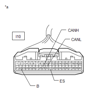
| *a | Front view of wire harness connector (to Combination Meter Assembly) |
(c) Measure the resistance according to the value(s) in the table below.
Standard Resistance:
| Terminal No. (Symbol) | Wiring Color | Terminal Description | Condition | Specified Condition |
|---|---|---|---|---|
| I10-29 (CANH) - I10-30 (CANL) | G - W | HIGH-level CAN bus line - LOW-level CAN bus line | Cable disconnected from negative (-) auxiliary battery terminal | 108 to 132 Ω |
| I10-29 (CANH) - I10-31 (ES) | G - W-B | HIGH-level CAN bus line - GND | Cable disconnected from negative (-) auxiliary battery terminal | 200 Ω or higher |
| I10-30 (CANL) - I10-31 (ES) | W - W-B | LOW-level CAN bus line - GND | Cable disconnected from negative (-) auxiliary battery terminal | 200 Ω or higher |
| I10-29 (CANH) - I10-22 (B) | G - Y | HIGH-level CAN bus line - Auxiliary battery positive (+) | Cable disconnected from negative (-) auxiliary battery terminal | 6 kΩ or higher |
| I10-30 (CANL) - I10-22 (B) | W - Y | LOW-level CAN bus line - Auxiliary battery positive (+) | Cable disconnected from negative (-) auxiliary battery terminal | 6 kΩ or higher |
PARKING BRAKE ECU ASSEMBLY
Refer to Terminals of ECU.
Click here
(a) Disconnect the cable from the negative (-) auxiliary battery terminal.
(b) Disconnect the parking brake ECU assembly connectors.
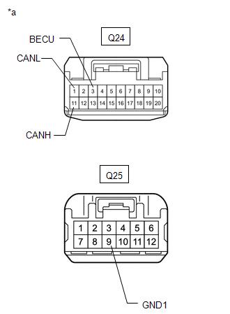
| *a | Front view of wire harness connector (to Parking Brake ECU Assembly) |
(c) Measure the resistance according to the value(s) in the table below.
Standard Resistance:
| Terminal No. (Symbol) | Wiring Color | Terminal Description | Condition | Specified Condition |
|---|---|---|---|---|
| Q24-11 (CANH) - Q24-1 (CANL) | B - W | HIGH-level CAN bus line - LOW-level CAN bus line | Cable disconnected from negative (-) auxiliary battery terminal | 54 to 69 Ω |
| Q24-11 (CANH) - Q25-9 (GND1) | B - W-B | HIGH-level CAN bus line - GND | Cable disconnected from negative (-) auxiliary battery terminal | 200 Ω or higher |
| Q24-1 (CANL) - Q25-9 (GND1) | W - W-B | LOW-level CAN bus line - GND | Cable disconnected from negative (-) auxiliary battery terminal | 200 Ω or higher |
| Q24-11 (CANH) - Q24-3 (BECU) | B - B | HIGH-level CAN bus line - Auxiliary battery positive (+) | Cable disconnected from negative (-) auxiliary battery terminal | 6 kΩ or higher |
| Q24-1 (CANL) - Q24-3 (BECU) | W - B | LOW-level CAN bus line - Auxiliary battery positive (+) | Cable disconnected from negative (-) auxiliary battery terminal | 6 kΩ or higher |
STEREO COMPONENT EQUALIZER ASSEMBLY (w/ ASC System)
Refer to Terminals of ECU.
Click here
(a) Disconnect the cable from the negative (-) auxiliary battery terminal.
(b) Disconnect the stereo component equalizer assembly connector.
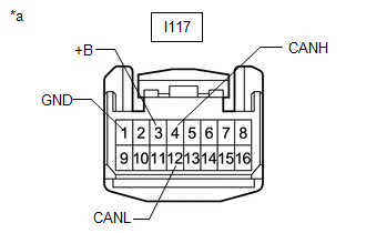
| *a | Front view of wire harness connector (to Stereo Component Equalizer Assembly) |
(c) Measure the resistance according to the value(s) in the table below.
Standard Resistance:
| Terminal No. (Symbol) | Wiring Color | Terminal Description | Condition | Specified Condition |
|---|---|---|---|---|
| I117-4 (CANH) - I117-12 (CANL) | R - W | HIGH-level CAN bus line - LOW-level CAN bus line | Cable disconnected from negative (-) auxiliary battery terminal | 54 to 69 Ω |
| I117-4 (CANH) - I117-1 (GND) | R - W-B | HIGH-level CAN bus line - GND | Cable disconnected from negative (-) auxiliary battery terminal | 200 Ω or higher |
| I117-12 (CANL) - I117-1 (GND) | W - W-B | LOW-level CAN bus line - GND | Cable disconnected from negative (-) auxiliary battery terminal | 200 Ω or higher |
| I117-4 (CANH) - I117-3 (+B) | R - W | HIGH-level CAN bus line - Auxiliary battery positive (+) | Cable disconnected from negative (-) auxiliary battery terminal | 6 kΩ or higher |
| I117-12 (CANL) - I117-3 (+B) | W - W | LOW-level CAN bus line - Auxiliary battery positive (+) | Cable disconnected from negative (-) auxiliary battery terminal | 6 kΩ or higher |
CLEARANCE WARNING ECU ASSEMBLY (w/ Intuitive Parking Assist System)
Refer to Terminals of ECU.
Click here
(a) Disconnect the cable from the negative (-) auxiliary battery terminal.
(b) Disconnect the clearance warning ECU assembly connector.
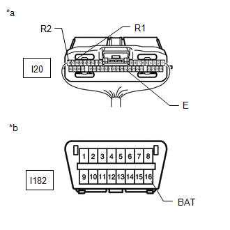
| *a | Rear view of wire harness connector (to Clearance Warning ECU Assembly) |
| *b | Front view of DLC3 |
(c) Measure the resistance according to the value(s) in the table below.
Standard Resistance:
| Terminal No. (Symbol) | Wiring Color | Terminal Description | Condition | Specified Condition |
|---|---|---|---|---|
| I20-17 (R1) - I20-18 (R2) | R - W | HIGH-level CAN bus line - LOW-level CAN bus line | Cable disconnected from negative (-) auxiliary battery terminal | 54 to 69 Ω |
| I20-17 (R1) - I20-27 (E) | R - W-B | HIGH-level CAN bus line - GND | Cable disconnected from negative (-) auxiliary battery terminal | 200 Ω or higher |
| I20-18 (R2) - I20-27 (E) | W - W-B | LOW-level CAN bus line - GND | Cable disconnected from negative (-) auxiliary battery terminal | 200 Ω or higher |
| I20-17 (R1) - I182-16 (BAT) | R - L | HIGH-level CAN bus line - Auxiliary battery positive (+) | Cable disconnected from negative (-) auxiliary battery terminal | 6 kΩ or higher |
| I20-18 (R2) - I182-16 (BAT) | W - L | LOW-level CAN bus line - Auxiliary battery positive (+) | Cable disconnected from negative (-) auxiliary battery terminal | 6 kΩ or higher |
PARKING ASSIST ECU (w/ Panoramic View Monitor System)
Refer to Terminals of ECU.
Click here
(a) Disconnect the cable from the negative (-) auxiliary battery terminal.
(b) Disconnect the parking assist ECU connector.
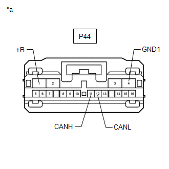
| *a | Front view of wire harness connector (to Parking Assist ECU) |
(c) Measure the resistance according to the value(s) in the table below.
Standard Resistance:
| Terminal No. (Symbol) | Wiring Color | Terminal Description | Condition | Specified Condition |
|---|---|---|---|---|
| P44-11 (CANH) - P44-12 (CANL) | G - W | HIGH-level CAN bus line - LOW-level CAN bus line | Cable disconnected from negative (-) auxiliary battery terminal | 54 to 69 Ω |
| P44-11 (CANH) - P44-4 (GND1) | G - W-B | HIGH-level CAN bus line - GND | Cable disconnected from negative (-) auxiliary battery terminal | 200 Ω or higher |
| P44-12 (CANL) - P44-4 (GND1) | W - W-B | LOW-level CAN bus line - GND | Cable disconnected from negative (-) auxiliary battery terminal | 200 Ω or higher |
| P44-11 (CANH) - P41 (+B) | G - L | HIGH-level CAN bus line - Auxiliary battery positive (+) | Cable disconnected from negative (-) auxiliary battery terminal | 6 kΩ or higher |
| P44-12 (CANL) - P44-1 (+B) | W - L | LOW-level CAN bus line - Auxiliary battery positive (+) | Cable disconnected from negative (-) auxiliary battery terminal | 6 kΩ or higher |
FORWARD RECOGNITION CAMERA (w/ Pre-collision System)
Refer to Terminals of ECU.
Click here
(a) Disconnect the cable from the negative (-) auxiliary battery terminal.
(b) Disconnect the forward recognition camera connector.
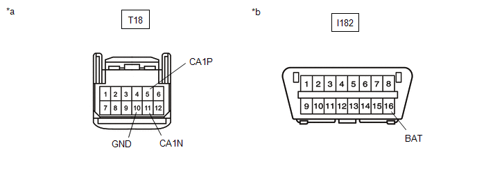
| *a | Front view of wire harness connector (to Forward Recognition Camera) | *b | Front view of DLC3 |
(c) Measure the resistance according to the value(s) in the table below.
Standard Resistance:
| Terminal No. (Symbol) | Wiring Color | Terminal Description | Condition | Specified Condition |
|---|---|---|---|---|
| T18-5 (CA1P) - T18-11 (CA1N) | B - W | HIGH-level CAN bus line - LOW-level CAN bus line | Cable disconnected from negative (-) auxiliary battery terminal | 54 to 69 Ω |
| T18-5 (CA1P) - T18-10 (GND) | B - W-B | HIGH-level CAN bus line - GND | Cable disconnected from negative (-) auxiliary battery terminal | 200 Ω or higher |
| T18-11 (CA1N) - T18-10 (GND) | W - W-B | LOW-level CAN bus line - GND | Cable disconnected from negative (-) auxiliary battery terminal | 200 Ω or higher |
| T18-5 (CA1P) - I182-16 (BAT) | B - L | HIGH-level CAN bus line - Auxiliary battery positive (+) | Cable disconnected from negative (-) auxiliary battery terminal | 6 kΩ or higher |
| T18-11 (CA1N) - I182-16 (BAT) | W - L | LOW-level CAN bus line - Auxiliary battery positive (+) | Cable disconnected from negative (-) auxiliary battery terminal | 6 kΩ or higher |
BLIND SPOT MONITOR SENSOR LH (w/ Blind Spot Monitor System)
Refer to Terminals of ECU.
Click here
(a) Disconnect the cable from the negative (-) auxiliary battery terminal.
(b) Disconnect the blind spot monitor sensor LH connector.
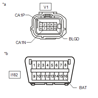
| *a | Front view of wire harness connector (to Blind Spot Monitor Sensor LH) |
| *b | Front view of DLC3 |
(c) Measure the resistance according to the value(s) in the table below.
Standard Resistance:
| Terminal No. (Symbol) | Wiring Color | Terminal Description | Condition | Specified Condition |
|---|---|---|---|---|
| V1-2 (CA1P) - V1-7 (CA1N) | R - W | HIGH-level CAN bus line - LOW-level CAN bus line | Cable disconnected from negative (-) auxiliary battery terminal | 54 to 69 Ω |
| V1-2 (CA1P) - V1-10 (BLGD) | R - W-B | HIGH-level CAN bus line - GND | Cable disconnected from negative (-) auxiliary battery terminal | 200 Ω or higher |
| V1-7 (CA1N) - V1-10 (BLGD) | W - W-B | LOW-level CAN bus line - GND | Cable disconnected from negative (-) auxiliary battery terminal | 200 Ω or higher |
| V1-2 (CA1P) - I182-16 (BAT) | R - L | HIGH-level CAN bus line - Auxiliary battery positive (+) | Cable disconnected from negative (-) auxiliary battery terminal | 6 kΩ or higher |
| V1-7 (CA1N) - I182-16 (BAT) | W - L | LOW-level CAN bus line - Auxiliary battery positive (+) | Cable disconnected from negative (-) auxiliary battery terminal | 6 kΩ or higher |
DCM (TELEMATICS TRANSCEIVER) (w/ Telematics Transceiver)
Refer to Terminals of ECU.
Click here
(a) Disconnect the cable from the negative (-) auxiliary battery terminal.
(b) Disconnect the DCM (telematics transceiver) connector.
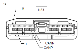
| *a | Front view of wire harness connector (to DCM [Telematics Transceiver]) |
(c) Measure the resistance according to the value(s) in the table below.
Standard Resistance:
| Terminal No. (Symbol) | Wiring Color | Terminal Description | Condition | Specified Condition |
|---|---|---|---|---|
| I183-25 (CANP) - I183-26 (CANN) | Y - W | HIGH-level CAN bus line - LOW-level CAN bus line | Cable disconnected from negative (-) auxiliary battery terminal | 54 to 69 Ω |
| I183-25 (CANP) - I183-20 (E) | Y - W-B | HIGH-level CAN bus line - GND | Cable disconnected from negative (-) auxiliary battery terminal | 200 Ω or higher |
| I183-26 (CANN) - I183-20 (E) | W - W-B | LOW-level CAN bus line - GND | Cable disconnected from negative (-) auxiliary battery terminal | 200 Ω or higher |
| I183-25 (CANP) - I183-1 (+B) | Y - Y | HIGH-level CAN bus line - Auxiliary battery positive (+) | Cable disconnected from negative (-) auxiliary battery terminal | 6 kΩ or higher |
| I183-26 (CANN) - I183-1 (+B) | W - Y | LOW-level CAN bus line - Auxiliary battery positive (+) | Cable disconnected from negative (-) auxiliary battery terminal | 6 kΩ or higher |
BUS BUFFER ECU (w/ Bus Buffer ECU)
(a) Disconnect the cable from the negative (-) auxiliary battery terminal.
(b) Disconnect the bus buffer ECU connector.
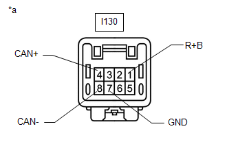
| *a | Front view of wire harness connector (to Bus Buffer ECU) |
(c) Measure the resistance according to the value(s) in the table below.
Standard Resistance:
| Terminal No. (Symbol) | Wiring Color | Terminal Description | Condition | Specified Condition |
|---|---|---|---|---|
| I130-4 (CAN+) - I130-8 (CAN-) | B - W | HIGH-level CAN bus line - LOW-level CAN bus line | Cable disconnected from negative (-) auxiliary battery terminal | 54 to 69 Ω |
| I130-4 (CAN+) - I130-7 (GND) | B - W-B | HIGH-level CAN bus line - GND | Cable disconnected from negative (-) auxiliary battery terminal | 200 Ω or higher |
| I130-8 (CAN-) - I130-7 (GND) | W - W-B | LOW-level CAN bus line - GND | Cable disconnected from negative (-) auxiliary battery terminal | 200 Ω or higher |
| I130-4 (CAN+) - I130-1 (R+B) | B - V | HIGH-level CAN bus line - Auxiliary battery positive (+) | Cable disconnected from negative (-) auxiliary battery terminal | 6 kΩ or higher |
| I130-8 (CAN-) - I130-1 (R+B) | W - V | LOW-level CAN bus line - Auxiliary battery positive (+) | Cable disconnected from negative (-) auxiliary battery terminal | 6 kΩ or higher |
OUTER MIRROR CONTROL ECU ASSEMBLY RH (w/ Memory)
Refer to Terminals of ECU.
Click here
(a) Disconnect the cable from the negative (-) auxiliary battery terminal.
(b) Disconnect the outer mirror control ECU assembly RH connector.
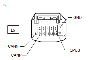
| *a | Front view of wire harness connector (to Outer Mirror Control ECU Assembly RH) |
(c) Measure the resistance according to the value(s) in the table below.
Standard Resistance:
| Terminal No. (Symbol) | Wiring Color | Terminal Description | Condition | Specified Condition |
|---|---|---|---|---|
| L5-9 (CANP) - L5-8 (CANN) | R - W | HIGH-level CAN bus line - LOW-level CAN bus line | Cable disconnected from negative (-) auxiliary battery terminal | 54 to 69 Ω |
| L5-9 (CANP) - L5-7 (GND) | R - W-B | HIGH-level CAN bus line - GND | Cable disconnected from negative (-) auxiliary battery terminal | 200 Ω or higher |
| L5-8 (CANN) - L5-7 (GND) | W - W-B | LOW-level CAN bus line - GND | Cable disconnected from negative (-) auxiliary battery terminal | 200 Ω or higher |
| L5-9 (CANP) - L5-6 (CPUB) | R - B | HIGH-level CAN bus line - Auxiliary battery positive (+) | Cable disconnected from negative (-) auxiliary battery terminal | 6 kΩ or higher |
| L5-8 (CANN) - L5-6 (CPUB) | W - B | LOW-level CAN bus line - Auxiliary battery positive (+) | Cable disconnected from negative (-) auxiliary battery terminal | 6 kΩ or higher |
OUTER MIRROR CONTROL ECU ASSEMBLY LH (w/ Memory)
Refer to Terminals of ECU.
Click here
(a) Disconnect the cable from the negative (-) auxiliary battery terminal.
(b) Disconnect the outer mirror control ECU assembly LH connector.
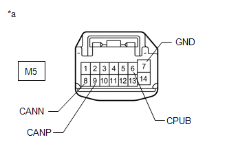
| *a | Front view of wire harness connector (to Outer Mirror Control ECU Assembly LH) |
(c) Measure the resistance according to the value(s) in the table below.
Standard Resistance:
| Terminal No. (Symbol) | Wiring Color | Terminal Description | Condition | Specified Condition |
|---|---|---|---|---|
| M5-9 (CANP) - M5-8 (CANN) | B - W | HIGH-level CAN bus line - LOW-level CAN bus line | Cable disconnected from negative (-) auxiliary battery terminal | 54 to 69 Ω |
| M5-9 (CANP) - M5-7 (GND) | B - W-B | HIGH-level CAN bus line - GND | Cable disconnected from negative (-) auxiliary battery terminal | 200 Ω or higher |
| M5-8 (CANN) - M5-7 (GND) | W - W-B | LOW-level CAN bus line - GND | Cable disconnected from negative (-) auxiliary battery terminal | 200 Ω or higher |
| M5-9 (CANP) - M5-6 (CPUB) | B - GR | HIGH-level CAN bus line - Auxiliary battery positive (+) | Cable disconnected from negative (-) auxiliary battery terminal | 6 kΩ or higher |
| M5-8 (CANN) - M5-6 (CPUB) | W - GR | LOW-level CAN bus line - Auxiliary battery positive (+) | Cable disconnected from negative (-) auxiliary battery terminal | 6 kΩ or higher |
MULTIPLEX NETWORK DOOR ECU (w/ Power Back Door System)
Refer to Terminals of ECU.
Click here
(a) Disconnect the cable from the negative (-) auxiliary battery terminal.
(b) Disconnect the multiplex network door ECU connectors.
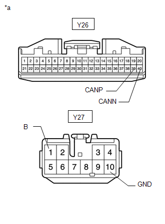
| *a | Front view of wire harness connector (to Multiplex Network Door ECU) |
(c) Measure the resistance according to the value(s) in the table below.
Standard Resistance:
| Terminal No. (Symbol) | Wiring Color | Terminal Description | Condition | Specified Condition |
|---|---|---|---|---|
| Y26-39 (CANP) - Y27-40 (CANN) | G - W | HIGH-level CAN bus line - LOW-level CAN bus line | Cable disconnected from negative (-) auxiliary battery terminal | 54 to 69 Ω |
| Y26-39 (CANP) - Y27-10 (GND) | G - W-B | HIGH-level CAN bus line - GND | Cable disconnected from negative (-) auxiliary battery terminal | 200 Ω or higher |
| Y26-40 (CANN) - Y27-10 (GND) | W - W-B | LOW-level CAN bus line - GND | Cable disconnected from negative (-) auxiliary battery terminal | 200 Ω or higher |
| Y26-39 (CANP) - Y27-1 (B) | G - LA-W | HIGH-level CAN bus line - Auxiliary battery positive (+) | Cable disconnected from negative (-) auxiliary battery terminal | 6 kΩ or higher |
| Y26-40 (CANN) - Y27-1 (B) | W - LA-W | LOW-level CAN bus line - Auxiliary battery positive (+) | Cable disconnected from negative (-) auxiliary battery terminal | 6 kΩ or higher |
FRONT POWER SEAT SWITCH (for Driver Side) (w/ Memory)
Refer to Terminals of ECU.
Click here
(a) Disconnect the cable from the negative (-) auxiliary battery terminal.
(b) Disconnect the front power seat switch (for driver side) connectors.
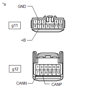
| *a | Front view of wire harness connector (to Front Power Seat Switch [for Driver Side]) |
(c) Measure the resistance according to the value(s) in the table below.
Standard Resistance:
| Terminal No. (Symbol) | Wiring Color | Terminal Description | Condition | Specified Condition |
|---|---|---|---|---|
| g12-8 (CANP) - g12-7 (CANN) | L - W | HIGH-level CAN bus line - LOW-level CAN bus line | Cable disconnected from negative (-) auxiliary battery terminal | 54 to 69 Ω |
| g12-8 (CANP) - g11-2 (GND) | L - W-B | HIGH-level CAN bus line - GND | Cable disconnected from negative (-) auxiliary battery terminal | 200 Ω or higher |
| g12-7 (CANN) - g11-2 (GND) | W - W-B | LOW-level CAN bus line - GND | Cable disconnected from negative (-) auxiliary battery terminal | 200 Ω or higher |
| g12-8 (CANP) - g11-7 (+B) | L - W | HIGH-level CAN bus line - Auxiliary battery positive (+) | Cable disconnected from negative (-) auxiliary battery terminal | 6 kΩ or higher |
| g12-7 (CANN) - g11-7 (+B) | W - W | LOW-level CAN bus line - Auxiliary battery positive (+) | Cable disconnected from negative (-) auxiliary battery terminal | 6 kΩ or higher |
MULTIPLEX TILT AND TELESCOPIC ECU (for Power Tilt and Power Telescopic Steering Column)
Refer to Terminals of ECU.
Click here
(a) Disconnect the cable from the negative (-) auxiliary battery terminal.
(b) Disconnect the multiplex tilt and telescopic ECU connector.
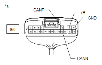
| *a | Rear view of wire harness connector (to Multiplex Tilt and Telescopic ECU) |
(c) Measure the resistance according to the value(s) in the table below.
Standard Resistance:
| Terminal No. (Symbol) | Wiring Color | Terminal Description | Condition | Specified Condition |
|---|---|---|---|---|
| I60-3 (CANP) - I60-11 (CANN) | G - W | HIGH-level CAN bus line - LOW-level CAN bus line | Cable disconnected from negative (-) auxiliary battery terminal | 54 to 69 Ω |
| I60-3 (CANP) - I60-1 (GND) | G - W-B | HIGH-level CAN bus line - GND | Cable disconnected from negative (-) auxiliary battery terminal | 200 Ω or higher |
| I60-11 (CANN) - I60-1 (GND) | W - W-B | LOW-level CAN bus line - GND | Cable disconnected from negative (-) auxiliary battery terminal | 200 Ω or higher |
| I60-3 (CANP) - I60-2 (+B) | G - Y | HIGH-level CAN bus line - Auxiliary battery positive (+) | Cable disconnected from negative (-) auxiliary battery terminal | 6 kΩ or higher |
| I60-11 (CANN) - I60-2 (+B) | W - Y | LOW-level CAN bus line - Auxiliary battery positive (+) | Cable disconnected from negative (-) auxiliary battery terminal | 6 kΩ or higher |
HEADLIGHT ECU SUB-ASSEMBLY LH (for Triple Beam Headlight)
Refer to Terminals of ECU.
Click here
(a) Disconnect the cable from the negative (-) auxiliary battery terminal.
(b) Disconnect the headlight ECU sub-assembly LH connector.
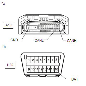
| *a | Front view of wire harness connector (to Headlight ECU Sub-assembly LH) |
| *b | Front view of DLC3 |
(c) Measure the resistance according to the value(s) in the table below.
Standard Resistance:
| Terminal No. (Symbol) | Wiring Color | Terminal Description | Condition | Specified Condition |
|---|---|---|---|---|
| A19-24 (CANH) - A19-23 (CANL) | B - R | HIGH-level CAN bus line - LOW-level CAN bus line | Cable disconnected from negative (-) auxiliary battery terminal | 54 to 69 Ω |
| A19-24 (CANH) - A19-12 (GND) | B - W-B | HIGH-level CAN bus line - GND | Cable disconnected from negative (-) auxiliary battery terminal | 200 Ω or higher |
| A19-23 (CANL) - A19-12 (GND) | R - W-B | LOW-level CAN bus line - GND | Cable disconnected from negative (-) auxiliary battery terminal | 200 Ω or higher |
| A19-24 (CANH) - I182-16 (BAT) | B - L | HIGH-level CAN bus line - Auxiliary battery positive (+) | Cable disconnected from negative (-) auxiliary battery terminal | 6 kΩ or higher |
| A19-23 (CANL) - I182-16 (BAT) | R - L | LOW-level CAN bus line - Auxiliary battery positive (+) | Cable disconnected from negative (-) auxiliary battery terminal | 6 kΩ or higher |
MILLIMETER WAVE RADAR SENSOR ASSEMBLY (w/ Pre-collision System)
Refer to Terminals of ECU.
Click here
(a) Disconnect the cable from the negative (-) auxiliary battery terminal.
(b) Disconnect the millimeter wave radar sensor assembly connector.
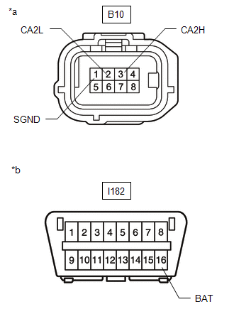
| *a | Front view of wire harness connector (to Millimeter Wave Radar Sensor Assembly) |
| *b | Front view of DLC3 |
(c) Measure the resistance according to the value(s) in the table below.
Standard Resistance:
| Terminal No. (Symbol) | Wiring Color | Terminal Description | Condition | Specified Condition |
|---|---|---|---|---|
| B10-3 (CA2H) - B10-2 (CA2L) | L - B | HIGH-level CAN bus line - LOW-level CAN bus line | Cable disconnected from negative (-) auxiliary battery terminal | 54 to 69 Ω |
| B10-3 (CA2H) - B10-1 (SGND) | L - W | HIGH-level CAN bus line - GND | Cable disconnected from negative (-) auxiliary battery terminal | 200 Ω or higher |
| B10-2 (CA2L) - B10-1 (SGND) | B - W | LOW-level CAN bus line - GND | Cable disconnected from negative (-) auxiliary battery terminal | 200 Ω or higher |
| B10-3 (CA2H) - I182-16 (BAT) | L - L | HIGH-level CAN bus line - Auxiliary battery positive (+) | Cable disconnected from negative (-) auxiliary battery terminal | 6 kΩ or higher |
| B10-2 (CA2L) - I182-16 (BAT) | B - L | LOW-level CAN bus line - Auxiliary battery positive (+) | Cable disconnected from negative (-) auxiliary battery terminal | 6 kΩ or higher |
METER MIRROR SUB-ASSEMBLY (w/ Headup Display)
Refer to Terminals of ECU.
Click here
(a) Disconnect the cable from the negative (-) auxiliary battery terminal.
(b) Disconnect the meter mirror sub-assembly connector.
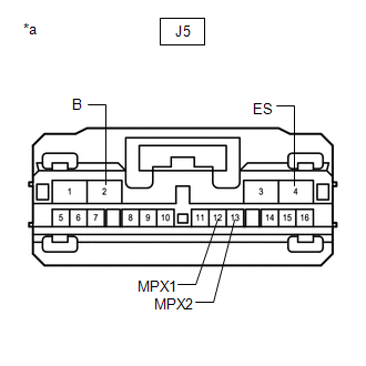
| *a | Front view of wire harness connector (to Meter Mirror Sub-assembly) |
(c) Measure the resistance according to the value(s) in the table below.
Standard Resistance:
| Terminal No. (Symbol) | Wiring Color | Terminal Description | Condition | Specified Condition |
|---|---|---|---|---|
| J5-12 (MPX1) - J5-13 (MPX2) | L - LG | HIGH-level CAN bus line - LOW-level CAN bus line | Cable disconnected from negative (-) auxiliary battery terminal | 54 to 69 Ω |
| J5-12 (MPX1) - J5-4 (ES) | L - W-B | HIGH-level CAN bus line - Ground | Cable disconnected from negative (-) auxiliary battery terminal | 200 Ω or higher |
| J5-13 (MPX2) - J5-4 (ES) | LG - W-B | LOW-level CAN bus line - Ground | Cable disconnected from negative (-) auxiliary battery terminal | 200 Ω or higher |
| J5-12 (MPX1) - J5-2 (B) | L - G | HIGH-level CAN bus line - Auxiliary battery positive (+) | Cable disconnected from negative (-) auxiliary battery terminal | 6 kΩ or higher |
| J5-13 (MPX2) - J5-2 (B) | LG - G | LOW-level CAN bus line - Auxiliary battery positive (+) | Cable disconnected from negative (-) auxiliary battery terminal | 6 kΩ or higher |
REAR TELEVISION CAMERA ASSEMBLY
Refer to Terminals of ECU.
w/ Parking Assist Monitor System: Click here
w/ Panoramic View Monitor System: Click here
(a) Disconnect the cable from the negative (-) auxiliary battery terminal.
(b) Disconnect the rear television camera assembly connector.
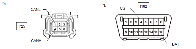
| *a | Front view of wire harness connector (to Rear Television Camera Assembly) | *b | Front view of DLC3 |
(c) Measure the resistance according to the value(s) in the table below.
Standard Resistance:
| Terminal No. (Symbol) | Wiring Color | Terminal Description | Condition | Specified Condition |
|---|---|---|---|---|
| Y25-4 (CANH) - Y25-1 (CANL) | G - GR | HIGH-level CAN bus line - LOW-level CAN bus line | Cable disconnected from negative (-) auxiliary battery terminal | 54 to 69 Ω |
| Y25-4 (CANH) - I182-4 (CG) | G - W-B | HIGH-level CAN bus line - Ground | Cable disconnected from negative (-) auxiliary battery terminal | 200 Ω or higher |
| Y25-1 (CANL) - I182-4 (CG) | GR - W-B | LOW-level CAN bus line - Ground | Cable disconnected from negative (-) auxiliary battery terminal | 200 Ω or higher |
| Y25-4 (CANH) - I182-16 (BAT) | G - L | HIGH-level CAN bus line - Auxiliary battery positive (+) | Cable disconnected from negative (-) auxiliary battery terminal | 6 kΩ or higher |
| Y25-1 (CANL) - I182-16 (BAT) | GR - L | LOW-level CAN bus line - Auxiliary battery positive (+) | Cable disconnected from negative (-) auxiliary battery terminal | 6 kΩ or higher |
ABSORBER CONTROL ECU (w/ Adaptive Variable Suspension System)
Refer to Terminals of ECU.
Click here
(a) Disconnect the cable from the negative (-) auxiliary battery terminal.
(b) Disconnect the absorber control ECU connector.
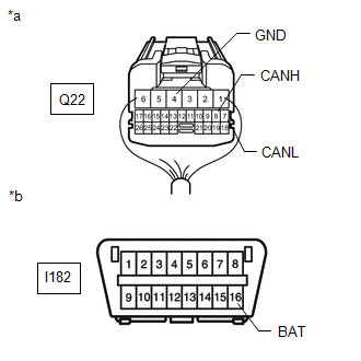
| *a | Rear view of wire harness connector (to Absorber Control ECU) |
| *b | Front view of DLC3 |
(c) Measure the resistance according to the value(s) in the table below.
Standard Resistance:
| Terminal No. (Symbol) | Wiring Color | Terminal Description | Condition | Specified Condition |
|---|---|---|---|---|
| Q22-8 (CANH) - Q22-7 (CANL) | B - W | HIGH-level CAN bus line - LOW-level CAN bus line | Cable disconnected from negative (-) auxiliary battery terminal | 54 to 69 Ω |
| Q22-8 (CANH) - Q22-4 (GND) | B - W-B | HIGH-level CAN bus line - GND | Cable disconnected from negative (-) auxiliary battery terminal | 200 Ω or higher |
| Q22-7 (CANL) - Q22-4 (GND) | W - W-B | LOW-level CAN bus line - GND | Cable disconnected from negative (-) auxiliary battery terminal | 200 Ω or higher |
| Q22-8 (CANH) - I182-16 (BAT) | B - L | HIGH-level CAN bus line - Auxiliary battery positive (+) | Cable disconnected from negative (-) auxiliary battery terminal | 6 kΩ or higher |
| Q22-7 (CANL) - I182-16 (BAT) | W - L | LOW-level CAN bus line - Auxiliary battery positive (+) | Cable disconnected from negative (-) auxiliary battery terminal | 6 kΩ or higher |
VEHICLE APPROACHING SPEAKER CONTROLLER
Refer to Terminals of ECU.
Click here
(a) Disconnect the cable from the negative (-) auxiliary battery terminal.
(b) Disconnect the vehicle approaching speaker controller connector.
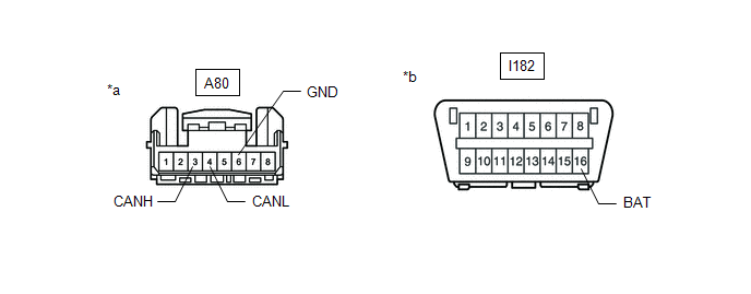
| *a | Front view of wire harness connector (to Vehicle Approaching Speaker Controller) | *b | Front view of DLC3 |
(c) Measure the resistance according to the value(s) in the table below.
Standard Resistance:
| Terminal No. (Symbol) | Wiring Color | Terminal Description | Condition | Specified Condition |
|---|---|---|---|---|
| A80-3 (CANH) - A80-4 (CANL) | V - W | HIGH-level CAN bus line - LOW-level CAN bus line | Cable disconnected from negative (-) auxiliary battery terminal | 54 to 69 Ω |
| A80-3 (CANH) - A80-6 (GND) | V - W-B | HIGH-level CAN bus line - GND | Cable disconnected from negative (-) auxiliary battery terminal | 200 Ω or higher |
| A80-4 (CANL) - A80-6 (GND) | W - W-B | LOW-level CAN bus line - GND | Cable disconnected from negative (-) auxiliary battery terminal | 200 Ω or higher |
| A80-3 (CANH) - I182-16 (BAT) | V - L | HIGH-level CAN bus line - Auxiliary battery positive (+) | Cable disconnected from negative (-) auxiliary battery terminal | 6 kΩ or higher |
| A80-4 (CANL) - I182-16 (BAT) | W - L | LOW-level CAN bus line - Auxiliary battery positive (+) | Cable disconnected from negative (-) auxiliary battery terminal | 6 kΩ or higher |
READ NEXT:
 Diagnosis System
DIAGNOSIS SYSTEM CHECK FOR INSTALLED SYSTEMS (ECUS AND SENSORS) THAT USE CAN COMMUNICATION (a) The systems (ECUs and sensors) that use CAN communication vary depending on the vehicle and optional equi
Dtc Combination Table
DTC COMBINATION TABLE HOW TO INTERPRET COMMUNICATION DTCS (DTCS THAT START WITH U) (a) If a CAN communication error cannot be reproduced, determine the suspected malfunctioning part using the DTCs sto
Dtc Check / Clear
DTC CHECK / CLEAR CHECK FOR DTC (a) Connect the Techstream to the DLC3. (b) Turn the power switch on (IG). (c) Turn the Techstream on. (d) Enter the following menus: Body Electrical / Central Gateway
SEE MORE:
USB Device Malfunction (B1585)
DESCRIPTION This DTC is stored when a malfunction occurs in a connected device. DTC No. Detection Item DTC Detection Condition Trouble Area B1585 USB Device Malfunction When one of the conditions below is met:
A non mass-storage class or incompatible protocol USB device is connec
Front Airbag Sensor Lost Communication (RH) (B1612,B1613)
DESCRIPTION The front airbag sensor RH circuit consists of the airbag ECU assembly and front airbag sensor RH. The front airbag sensor RH detects impacts to the vehicle and sends signals to the airbag ECU assembly to determine if the airbag should be deployed. DTC B1612 or B1613 is stored when a mal
