Lexus NX: Terminals Of Ecu
TERMINALS OF ECU
HINT:
Perform the inspection from the harness side with the connectors connected.
STEERING HEATER AND VIBRATION ECU
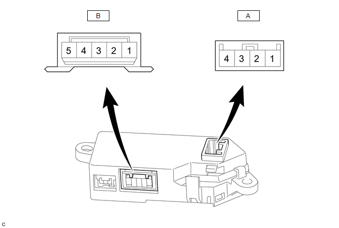
(a) Measure the voltage or resistance according to the value(s) in the table below.
| Terminal No. (Symbol) | Terminal Description | Condition | Specified Condition |
|---|---|---|---|
| A-4 (IG) - Body ground | IG power supply | Power switch on (IG) | 11 to 14 V |
| A-3 (SW) - Body ground | Steering heater switch input signal | Power switch on (IG), steering heater switch pressed and held | 11 to 14 V |
| A-2 (LED) - Body ground | LED output signal | Power switch on (IG), Heated steering wheel system operating | Below 3 V |
| A-1 (GND) - Body ground | Ground | Always | Below 1 Ω |
| B-5 (SH1) - Body ground | Heater output signal | Power switch on (IG), Heated steering wheel system operating | 11 to 14 V(*1) |
| B-3 (TH1) - Body ground | Thermistor input signal | Power switch on (IG), Heated steering wheel system operating | 2.5 to 4.8 V(*2) |
| B-2 (TH2) - Body ground | Thermistor ground | Power switch on (IG), Heated steering wheel system operating | Below 1 V |
| B-1 (SH2) - Body ground | Heater ground | Power switch on (IG), Heated steering wheel system operating | Below 1 V |
HINT:
- *1: The current to the heater turns ON/OFF depending on the temperature of the thermistor. As a result, it may take several minutes before a voltage value is output.
- *2: When ambient temperature is 0 to 40°C (32 to 104°F).
READ NEXT:
 Fail-safe Chart
FAIL-SAFE CHART MALFUNCTION DETECTION (a) Operation when malfunction is detected Content Operation Heater failure Overcurrent detection of drive element Heater output off Overheating
Steering Wheel does not Heat Up When Heated Steering Wheel Switch is Pressed
DESCRIPTION Click here WIRING DIAGRAM Click here CAUTION / NOTICE / HINT HINT:
Inspect the fuses for circuits related to this system before performing the following inspection procedure.
The
SEE MORE:
Precaution
PRECAUTION PRECAUTION FOR DISCONNECTING CABLE FROM NEGATIVE AUXILIARY BATTERY TERMINAL NOTICE:
After the power switch is turned off, there may be a waiting time before disconnecting the negative (-) auxiliary battery terminal.
Click here
When disconnecting and reconnecting the auxiliary batte
Dtc Check / Clear
DTC CHECK / CLEAR DTC CHECK (a) Connect the Techstream to the DLC3. (b) Turn the power switch on (IG). (c) Turn the Techstream on. (d) Enter the following menus: Body Electrical / Vehicle Proximity Notification System / Trouble Codes. Body Electrical > Vehicle Proximity Notification System > T
