- Shift lever in P
- Steering lock unlocked in advance by carrying key and turning power switch on (IG)
- After above conditions met, power switch turned off
Lexus NX: Terminals Of Ecu
TERMINALS OF ECU
TERMINAL INSPECTION

| *a | Component without harness connected (Steering Lock ECU (Steering Lock Actuator Assembly)) | - | - |
(a) Measure the voltage and resistance according to the value(s) in the table below.
| Terminal No. (Symbol) | Input/Output | Wiring Color | Terminal Description | Condition | Specified Condition | Related Data List Item |
|---|---|---|---|---|---|---|
| I2-1 (GND) - Body ground | - | W-B - Body ground | Ground | Always | Below 1 Ω | - |
| I2-3 (IGE) - I2-1 (GND) | Input | L - W-B | Steering lock motor activation command signal (motor activation command signal sent from certification ECU (smart key ECU assembly)) | Any door opened when conditions below met, and then steering lock motor activated: | Pulse generation (see waveform) | Smart Access
|
| I2-4 (SLP1) - I2-1 (GND) | Output | Y - W-B | Steering lock bar position signal (output signal from steering unlock sensor) | Steering locked → unlocked | 11 to 14 V → Below 1.5 V | Smart Access
|
| I2-5 (LIN) - I2-1 (GND) | Input/Output | G - W-B | LIN communication line | - | - | Smart Access
|
| I2-6 (IG2) - I2-1 (GND) | Input | P - W-B | Power source mode signal (IG2 power supply input for entire steering lock actuator assembly) | Power switch off → power switch on (IG) | Below 1 V → 11 to 14 V | - |
| I2-7 (B) - Body ground | Input | L - Body ground | Power source | Always | 11 to 14 V | - |
NOTICE:
There is 1 motor and 2 sensors built into the steering lock actuator assembly.
HINT:
- When taking measurements when the lock motor is stopped, it is not necessary to perform any operations.
-
In order to take measurements when the lock motor is operating, perform either of the following operations:
- To unlock the steering, carry the key and turn the power switch on (ACC) or on (IG).
- To lock the steering, turn the power switch off with the shift lever in P, and then open a door.
(1) Waveform
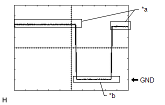
| *a | Steering Lock Motor not Operating |
| *b | Steering Lock Motor Operating |
| Item | Content |
|---|---|
| Tester Connection | I2-3 (IGE) - I2-1 (GND) |
| Tool Setting | 2 V/DIV., 200 ms./DIV. |
| Vehicle Condition | Steering lock motor not operating → Operating → Not operating |
READ NEXT:
 Diagnosis System
DIAGNOSIS SYSTEM DESCRIPTION NOTICE:
When using the Techstream with the power switch off to confirm DTCs or Data List information related to the smart access system with push button start, the Tech
Dtc Check / Clear
DTC CHECK / CLEAR NOTICE:
The steering lock ECU (steering lock actuator assembly) does not store history DTCs. If any DTCs are output, confirm and record them as soon as possible. Do not turn the p
Data List / Active Test
DATA LIST / ACTIVE TEST READ DATA LIST HINT: Using the Techstream to read the Data List allows the values or states of switches, sensors, actuators and other items to be read without removing any part
SEE MORE:
Automatic High Beam Camera (B124C)
DESCRIPTION The main body ECU (multiplex network body ECU) detects a high beam headlight illumination request signal of the automatic high beam system from the forward recognition camera. DTC No. Detection Item DTC Detection Condition Trouble Area B124C Automatic High Beam Camera Ma
Hybrid Powertrain Control Module (P0A1D-148)
DESCRIPTION The hybrid vehicle control ECU monitors its internal operation, it will store a DTC and perform fail-safe control if it detects the following malfunction. If the following DTC is output, replace the hybrid vehicle control ECU. DTC No. Detection Item DTC Detection Condition Troub
© 2016-2024 Copyright www.lexunx.com
