- Power switch on (IG)
- Intelligent clearance sonar system on
Lexus NX: Terminals Of Ecu
Lexus NX Service Manual / Audio & Visual & Telematics / Park Assist / Monitoring / Intelligent Clearance Sonar System / Terminals Of Ecu
TERMINALS OF ECU
CLEARANCE WARNING ECU ASSEMBLY

(a) Disconnect the I20 clearance warning ECU assembly connector.
(b) Measure the voltage and resistance on the wire harness side connector according to the value(s) in the table below.
| Terminal No. (Symbol) | Wiring Color | Terminal Description | Condition | Specified Condition |
|---|---|---|---|---|
| I20-1 (IG) - I20-30 (E) | BE - W-B | IG power source | Power switch off | Below 1 V |
| Power switch on (IG) | 11 to 14 V | |||
| I20-30 (E) - Body ground | W-B - Body ground | Ground | Always | Below 1 Ω |
(c) Reconnect the I20 clearance warning ECU assembly connector.
(d) Measure the voltage, resistance and check for pulses according to the value(s) in the table below.
| Terminal No. (Symbol) | Wiring Color | Terminal Description | Condition | Specified Condition |
|---|---|---|---|---|
| I20-4 (BOF) - I20-30 (E) | R - W-B | Power source for front sensor circuit | Power switch off | Below 1 V |
| | 11 to 14 V | |||
| I20-6 (E5) - I20-30 (E) | LG - W-B | Ground for front clearance sonar | Always | Below 1 Ω |
| I20-8 (SOF) - I20-30 (E) | V - W-B | Front sensor communication signal (Front clearance sonar sensor) |
| Pulse generation (Refer to waveform 1) |
| I20-14 (CBZ) - I20-13 (EF) | LG - L | No. 1 clearance warning buzzer signal | Buzzer sounding | Pulse generation (Refer to waveform 2) |
| I20-15 (BBZ) - I20-16 (ER) | SB - P | No. 2 clearance warning buzzer signal | Buzzer sounding | Pulse generation (Refer to waveform 2) |
| I20-22 (BOR) - I20-30 (E) | SB - W-B | Power source for rear sensor circuit | Power switch off | Below 1 V |
| 11 to 14 V | |||
| I20-23 (E1) - I20-30 (E) | L - W-B | Ground for rear clearance sonar | Always | Below 1 Ω |
| I20-24 (SOR) - I20-30 (E) | R - W-B | Rear sensor communication signal (Rear clearance sonar sensor) |
| Pulse generation (Refer to waveform 3) |
(e) Using an oscilloscope, check waveform 1.
(1) Waveform 1 (Reference)
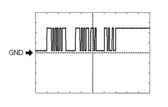
| Item | Content |
|---|---|
| Measurement terminal | I20-8 (SOF) - I20-30 (E) |
| Measurement setting | 5 V/DIV., 1 ms./DIV. |
| Condition |
|
(f) Using an oscilloscope, check waveform 2.
(1) Waveform 2 (Reference)
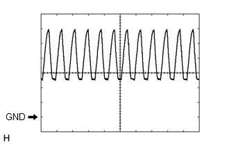
| Item | Content |
|---|---|
| Measurement terminal |
|
| Measurement setting | 2 V/DIV., 500 μs./DIV. |
| Condition | Buzzer sounding |
HINT:
The amplitude of the waveform changes according to the set volume.
(g) Using an oscilloscope, check waveform 3.
(1) Waveform 3 (Reference)
| Item | Content |
|---|---|
| Measurement terminal | I20-24 (SOR) - I20-30 (E) |
| Measurement setting | 5 V/DIV., 1 ms./DIV. |
| Condition |
|
COMBINATION METER ASSEMBLY
Click here .gif)
METER MIRROR SUB-ASSEMBLY (w/ Headup Display)
Click here
HYBRID VEHICLE CONTROL ECU
Click here
READ NEXT:
 Diagnosis System
DIAGNOSIS SYSTEM DESCRIPTION (a) Intelligent clearance sonar system data and Diagnostic Trouble Codes (DTCs) can be read from the Data Link Connector 3 (DLC3) of the vehicle. When the system seems to
Dtc Check / Clear
DTC CHECK / CLEAR CHECK DTC (a) Connect the Techstream to the DLC3. (b) Turn the power switch on (IG). (c) Turn the intelligent clearance sonar system on. (d) Turn the Techstream on. (e) Enter the fol
Fail-safe Chart
FAIL-SAFE CHART FAIL-SAFE FUNCTION (a) If a malfunction is detected in the intelligent clearance sonar system, the warning message "Parking Support Brake System Malfunction Visit Your Dealer" or "Park
SEE MORE:
Components
COMPONENTS ILLUSTRATION *1 DECK FLOOR BOX LH *2 NO. 3 DECK BOARD SUB-ASSEMBLY *3 REAR DECK FLOOR BOX *4 NEGATIVE AUXILIARY BATTERY TERMINAL N*m (kgf*cm, ft.*lbf): Specified torque - - ILLUSTRATION *1 DCM (TELEMATICS TRANSCEIVER) *2 MOBILEPHONE BATTERY
Electronic key battery
Replace the battery with a new one
if it is depleted.
■When the card key battery needs to be
replaced (if equipped)
The battery for the card key is available only
at Lexus dealers. Your Lexus dealer can
replace the battery for you.
■If the electronic key battery is depleted
The followi
© 2016-2024 Copyright www.lexunx.com
