Lexus NX: Theft Warning Siren Circuit
DESCRIPTION
The theft warning siren has an internal battery. If the vehicle auxiliary battery cable is disconnected or any of the communication lines are open, the theft warning siren detects this and sounds its siren.
Although the theft warning siren usually sounds by receiving a signal from the main body ECU (multiplex network body ECU), the theft warning siren can sound by its internal battery in case the vehicle auxiliary battery cable is disconnected.
The main body ECU (multiplex network body ECU) sends an arming signal to the theft warning siren while transferring to the armed state, and it also sends a disarming signal to the siren while switching to the disarmed state. Also, the main body ECU (multiplex network body ECU) can cause the theft warning siren to sound by sending an alarm signal during the alarm sounding state.
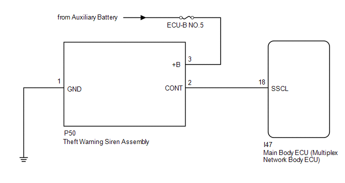
WIRING DIAGRAM
CAUTION / NOTICE / HINT
NOTICE:
- Inspect the fuses for circuits related to this system before performing the following inspection procedure.
-
If the main body ECU (multiplex network body ECU) is replaced, refer to Registration.
Click here
.gif)
PROCEDURE
| 1. | PERFORM ACTIVE TEST USING TECHSTREAM (SECURITY HORN2) |
(a) Connect the Techstream to the DLC3.
(b) Turn the power switch on (IG).
(c) Turn the Techstream on.
(d) Enter the following menus: Body Electrical / Main Body / Active Test.
(e) According to the display on the Techstream, perform the Active Test.
Body Electrical > Main Body > Active Test| Tester Display | Measurement Item | Control Range | Diagnostic Note |
|---|---|---|---|
| Security Horn2 | Theft warning siren assembly | ON or OFF | - |
| Tester Display |
|---|
| Security Horn2 |
OK:
The theft warning siren assembly sounds and stops correctly when operated through the Techstream.
| OK | .gif) | REPLACE MAIN BODY ECU (MULTIPLEX NETWORK BODY ECU) |
|
.gif)
| 2. | CHECK HARNESS AND CONNECTOR (THEFT WARNING SIREN ASSEMBLY - BATTERY AND BODY GROUND) |
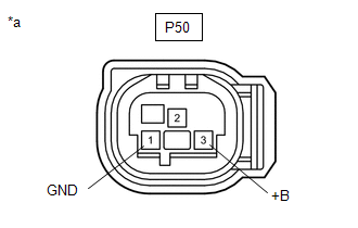
| (a) Disconnect the theft warning siren assembly connector. |
|
(b) Measure the voltage according to the value(s) in the table below.
Standard Voltage:
| Tester Connection | Switch Condition | Specified Condition |
|---|---|---|
| P50-3 (+B) - Body ground | Power switch off | 11 to 14 V |
(c) Measure the resistance according to the value(s) in the table below.
Standard Resistance:
| Tester Connection | Condition | Specified Condition |
|---|---|---|
| P50-1 (GND) - Body ground | Always | Below 1 Ω |
| NG | | REPAIR OR REPLACE HARNESS OR CONNECTOR |
|
| 3. | CHECK HARNESS AND CONNECTOR (THEFT WARNING SIREN ASSEMBLY - MAIN BODY ECU [MULTIPLEX NETWORK BODY ECU]) |
(a) Disconnect the P50 theft warning siren assembly connector.
(b) Disconnect the I47 main body ECU (multiplex network body ECU) connector.
(c) Measure the resistance according to the value(s) in the table below.
Standard Resistance:
| Tester Connection | Condition | Specified Condition |
|---|---|---|
| P50-2 (CONT) - I47-18 (SSCL) | Always | Below 1 Ω |
| P50-2 (CONT) - Body ground | Always | 10 kΩ or higher |
| I47-18 (SSCL) - Body ground | Always | 10 kΩ or higher |
| NG | | REPAIR OR REPLACE HARNESS OR CONNECTOR |
|
| 4. | CHECK THEFT WARNING SIREN ASSEMBLY |
(a) Temporarily replace the theft warning siren assembly with a new or normally functioning one.
Click here
(b) Check the operation of the theft warning siren assembly function.
OK:
Theft warning siren assembly function operates normally.
| OK | | END (THEFT WARNING SIREN ASSEMBLY WAS DEFECTIVE) |
| NG | | REPLACE MAIN BODY ECU (MULTIPLEX NETWORK BODY ECU) |
READ NEXT:
SEE MORE:
 Diagnosis System
DIAGNOSIS SYSTEM DESCRIPTION (a) Sliding roof system data and Diagnostic Trouble Codes (DTCs) can be read through the vehicle Data Link Connector 3 (DLC3). When the system seems to be malfunctioning, use the Techstream to check for malfunctions and perform repairs. CHECK DLC3 (a) Check the DLC3. Cli
Motor Electronics Coolant Temperature Sensor Circuit Low (P0A02-719,P0A03-720)
DESCRIPTION Refer to the description for DTC P0A01-726. Click here DTC No. Detection Item DTC Detection Condition Trouble Area MIL Warning Indicate P0A02-719 Motor Electronics Coolant Temperature Sensor Circuit Low Short to ground in the HV coolant temperature sensor circuit (
