Lexus NX: Tilt and Telescopic Manual Switch Circuit
DESCRIPTION
Different voltage values are sent to the multiplex tilt and telescopic ECU by operating the tilt and telescopic switch. The multiplex tilt and telescopic ECU then judges which motor and in which direction that motor should operate based on the voltage value.
WIRING DIAGRAM
.png)
PROCEDURE
| 1. | READ VALUE USING TECHSTREAM (TILT UP/DOWN SWITCH, TELESCOPIC SHORT/LONG SWITCH) |
(a) Turn the power switch off.
(b) Connect the Techstream to the DLC3.
(c) Turn the power switch on (IG).
(d) Turn the Techstream on.
(e) Check the tilt and telescopic switch.
(f) Enter the following menus: Body Electrical / Tilt & Telescopic / Data List.
Body Electrical > Tilt&Telescopic > Data List| Tester Display | Measurement Item | Range | Normal Condition | Diagnostic Note |
|---|---|---|---|---|
| Tilt Up Switch | Input state of tilt up switch | ON or OFF | ON: Tilt up switch activated OFF: Tilt up switch not activated | - |
| Tilt Down Switch | Input state of tilt down switch | ON or OFF | ON: Tilt down switch activated OFF: Tilt down switch not activated | - |
| Telesco Short Switch | Input state of telescopic contract switch | ON or OFF | ON: Telescopic contract switch activated OFF: Telescopic contract switch not activated | - |
| Telesco Long Switch | Input state of telescopic extend switch | ON or OFF | ON: Telescopic extend switch activated OFF: Telescopic extend switch not activated | - |
| Tester Display |
|---|
| Tilt Up Switch |
| Tilt Down Switch |
| Telesco Short Switch |
| Telesco Long Switch |
OK:
"ON" is displayed on the Techstream screen when each switch is turned on.
"OFF" is displayed on the Techstream screen when each switch is turned off.
| OK | .gif) | REPLACE MULTIPLEX TILT AND TELESCOPIC ECU |
.gif)
|
.gif)
| 2. | CHECK HARNESS AND CONNECTOR (MULTIPLEX TILT AND TELESCOPIC ECU - TILT AND TELESCOPIC SWITCH) |
(a) Disconnect the I60 multiplex tilt and telescopic ECU connector.
(b) Disconnect the I65 tilt and telescopic switch connector.
(c) Measure the resistance according to the value(s) in the table below.
Standard Resistance:
| Tester Connection | Condition | Specified Condition |
|---|---|---|
| I60-5 (VC) - I65-1 (VC) | Always | Below 1 Ω |
| I60-18 (MSW) - I65-3 (MSW) | Always | Below 1 Ω |
| I60-5 (VC) - Body ground | Always | 10 kΩ or higher |
| I60-18 (MSW) - Body ground | Always | 10 kΩ or higher |
| NG | | REPAIR OR REPLACE HARNESS OR CONNECTOR |
|
| 3. | CHECK MULTIPLEX TILT AND TELESCOPIC ECU (VC TERMINAL VOLTAGE) |
| (a) Reconnect the I60 multiplex tilt and telescopic ECU connector. |
|
.png)
(b) Measure the voltage according to the value(s) in the table below.
Standard Voltage:
| Tester Connection | Condition | Specified Condition |
|---|---|---|
| I60-5 (VC) - I60-18 (MSW) | Power switch on (IG) | 4.9 to 5.1 V |
| NG | | REPLACE MULTIPLEX TILT AND TELESCOPIC ECU |
|
| 4. | CHECK TILT AND TELESCOPIC SWITCH |
| (a) Remove the tilt and telescopic switch. Click here |
|
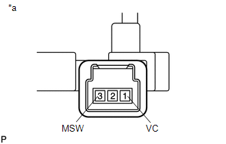
(b) Measure the resistance according to the value(s) in the table below.
Standard Resistance:
| Tester Connection | Condition | Specified Condition |
|---|---|---|
| 1 (VC) - 3 (MSW) | Tilt up | 342 to 378 Ω |
| Tilt down | 1890.5 to 2089.5 Ω | |
| Telescopic contract | 750.5 to 829.5 Ω | |
| Telescopic extend | 152 to 168 Ω |
| OK | | PROCEED TO NEXT SUSPECTED AREA SHOWN IN PROBLEM SYMPTOMS TABLE |
| NG | | REPLACE TILT AND TELESCOPIC SWITCH |
READ NEXT:
 IG Power Source Circuit
DESCRIPTION When the power switch is turned on (IG), the IG power source circuit supplies positive (+) voltage to the multiplex tilt and telescopic ECU. The multiplex tilt and telescopic ECU also rece
Components
COMPONENTS ILLUSTRATION *1 COLUMN HOLE COVER SILENCER SHEET *2 COMBINATION SWITCH ASSEMBLY WITH SPIRAL CABLE SUB-ASSEMBLY *3 ELECTRIC POWER STEERING COLUMN SUB-ASSEMBLY *4 LOWER ST
SEE MORE:
Seat belts
Make sure that all occupants are
wearing their seat belts before driving
the vehicle.
WARNING
Observe the following precautions to
reduce the risk of injury in the event of
sudden braking, sudden swerving or an
accident.
Failure to do so may cause death or serious
injury.
■Wearing a se
Operation Check
OPERATION CHECK INPUT SIGNAL CHECK (a) Connect the Techstream to the DLC3. (b) Check the cruise control main switch using the Data List function of the Techstream (ON-OFF, -SET, +RES and CANCEL). *a +RES *b -SET *c ON-OFF *d CANCEL Click here INSPECT CRUISE CONTROL MAIN
