Lexus NX: Vehicle Approaching Speaker
Components
COMPONENTS
ILLUSTRATION
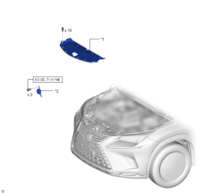
| *1 | RADIATOR SUPPORT OPENING COVER | *2 | VEHICLE APPROACHING SPEAKER ASSEMBLY |
 | N*m (kgf*cm, ft.*lbf): Specified torque | - | - |
Removal
REMOVAL
PROCEDURE
1. REMOVE RADIATOR SUPPORT OPENING COVER
(a) for Sport Package:
Click here .gif)
(b) except Sport Package:
Click here
2. REMOVE VEHICLE APPROACHING SPEAKER ASSEMBLY
(a) Remove the 2 bolts.
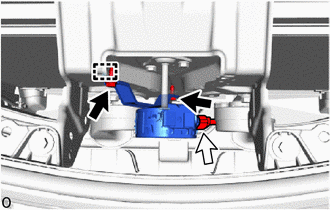
 | Bolt |
 | Connector |
(b) Detach the hook and remove the vehicle approaching speaker assembly.
NOTICE:
- When removing the vehicle approaching speaker assembly, take care not to damage it.
- Do not reuse a vehicle approaching speaker assembly that has been dropped or subjected to a strong shock.
- Do not push the vehicle approaching speaker assembly center area.
(c) Disconnect the connector.
Inspection
INSPECTION
PROCEDURE
1. INSPECT VEHICLE APPROACHING SPEAKER ASSEMBLY
| (a) Measure the resistance according to the value(s) in the table below. Standard Resistance:
|
|
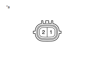
(b) Check the speaker and bracket for cracks or damage.
Installation
INSTALLATION
PROCEDURE
1. INSTALL VEHICLE APPROACHING SPEAKER ASSEMBLY
(a) Attach the hook and temporarily install the vehicle approaching speaker assembly.
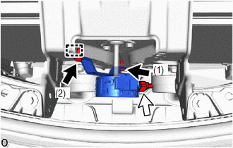
.png) | Bolt |
.png) | Connector |
NOTICE:
- When installing the vehicle approaching speaker assembly, take care not to damage it.
- Do not reuse a vehicle approaching speaker assembly that has been dropped or subjected to a strong shock.
- Do not push the vehicle approaching speaker assembly center area.
(b) Connect the connector.
(c) Install the vehicle approaching speaker assembly with the 2 bolts in the order shown in the illustration.
Torque:
8.0 N·m {82 kgf·cm, 71 in·lbf}
2. INSTALL RADIATOR SUPPORT OPENING COVER
(a) for Sport Package:
Click here .gif)
(b) except Sport Package:
Click here
READ NEXT:
 Components
COMPONENTS ILLUSTRATION *1 DECK FLOOR BOX LH *2 NO. 3 DECK BOARD SUB-ASSEMBLY *3 REAR DECK FLOOR BOX *4 NEGATIVE AUXILIARY BATTERY TERMINAL N*m (kgf*cm, ft.*lbf): Specified
Removal
REMOVAL PROCEDURE 1. PRECAUTION CAUTION: Be sure to read Precoution thoroughly before serving. Click here NOTICE: After the power switch is turned off, there may be a waiting time before disconnecti
SEE MORE:
AV Signal Stoppage (Low Battery Voltage) (B158F)
DESCRIPTION This DTC is stored when a video or audio signal is interrupted due to auxiliary battery voltage input to the radio receiver assembly dropping temporarily. DTC No. Detection Item DTC Detection Condition Trouble Area B158F AV Signal Stoppage (Low Battery Voltage) A video o
Diagnostic Trouble Code Chart
DIAGNOSTIC TROUBLE CODE CHART Automatic Headlight Beam Level Control System (for Triple Beam Headlight) DTC No. Detection Item Link B2410 Headlight Swivel Motor LH Communication Malfunction B2411 Headlight Swivel Motor RH Communication Malfunction B2415 Vehicle Spe
