Lexus NX: Vehicle Speed Signal Circuit between Stereo Component Amplifier and Combination Meter
DESCRIPTION
The stereo component amplifier assembly receives a vehicle speed signal from the combination meter assembly to control the ASL function.
HINT:
- A voltage of 12 V or 5 V is output from each ECU and then input to the combination meter assembly. The signal is changed to a pulse signal at the transistor in the combination meter assembly. Each ECU controls its respective systems based on this pulse signal.
- If a short occurs in any of the ECUs or in the wire harness connected to an ECU, all systems in the diagram below will not operate normally.
WIRING DIAGRAM
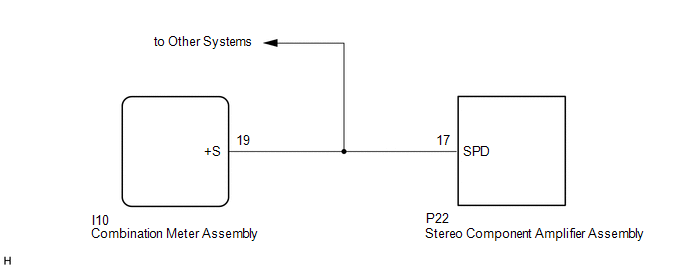
PROCEDURE
| 1. | CHECK COMBINATION METER ASSEMBLY (OUTPUT WAVEFORM) |
| (a) Check the output waveform. (1) Remove the combination meter assembly with the connector still connected. (2) Connect an oscilloscope to terminal I10-19 (+S) and body ground. (3) Turn the power switch on (IG). (4) Turn a wheel slowly. (5) Check the signal waveform according to the condition(s) in the table below.
OK: The waveform is similar to that shown in the illustration. HINT: When the system is functioning normally, one wheel revolution generates 4 pulses. As the vehicle speed increases, the width indicated by (A) in the illustration narrows. |
|
.png)
| NG | .gif) | GO TO METER / GAUGE SYSTEM |
.gif)
|
.gif)
| 2. | CHECK HARNESS AND CONNECTOR (STEREO COMPONENT AMPLIFIER ASSEMBLY - COMBINATION METER ASSEMBLY) |
(a) Disconnect the P22 stereo component amplifier assembly connector.
(b) Disconnect the I10 combination meter assembly connector.
(c) Measure the resistance according to the value(s) in the table below.
Standard Resistance:
| Tester Connection | Condition | Specified Condition |
|---|---|---|
| P22-17 (SPD) - I10-19 (+S) | Always | Below 1 Ω |
| OK | | PROCEED TO NEXT SUSPECTED AREA SHOWN IN PROBLEM SYMPTOMS TABLE |
| NG | | REPAIR OR REPLACE HARNESS OR CONNECTOR |
READ NEXT:
 Reverse Signal Circuit between Radio Receiver Assembly and Navigation ECU
DESCRIPTION This circuit includes the navigation ECU and radio and display receiver assembly. WIRING DIAGRAM PROCEDURE 1. CHECK HARNESS AND CONNECTOR (RADIO RECEIVER ASSEMBLY - NAVIGATION ECU)
Start Up Signal Circuit between Radio Receiver Assembly and Navigation ECU
DESCRIPTION This circuit includes the navigation ECU and radio and display receiver assembly. WIRING DIAGRAM PROCEDURE 1. CHECK HARNESS AND CONNECTOR (RADIO RECEIVER ASSEMBLY - NAVIGATION ECU)
Microphone Circuit
DESCRIPTION
The radio receiver assembly and telephone microphone assembly are connected to each other using the microphone connection detection signal lines.
Using this circuit, the DCM (telemati
SEE MORE:
Installation
INSTALLATION CAUTION / NOTICE / HINT CAUTION: Wear protective gloves. Sharp areas on the parts may injure your hands. PROCEDURE 1. INSTALL BENCH TYPE REAR SEAT CUSHION COVER (REAR SEAT CUSHION HEATER) HINT:
When installing the seat cover, refer to the precautions in order to prevent wrinkles from
Data List / Active Test
DATA LIST / ACTIVE TEST DATA LIST HINT: Using the Techstream to read the Data List allows the values or states of switches, sensors, actuators and other items to be read without removing any parts. This non-intrusive inspection can be very useful because intermittent conditions or signals may be dis
