Lexus NX: Voice Guidance does not Function
WIRING DIAGRAM
CAUTION / NOTICE / HINT
NOTICE:
When replacing the radio receiver assembly or navigation ECU, always replace it with a new one.
If a radio receiver assembly or navigation ECU which was installed to another vehicle is used, the following may occur:
- A communication malfunction DTC may be stored.
- The radio receiver assembly or navigation ECU may not operate normally.
PROCEDURE
| 1. | CHECK VOICE GUIDANCE SETTING |
(a) Check that the voice guidance settings are not off.
OK:
Voice guidance settings are not off.
| NG | .gif) | CHANGE VOICE GUIDANCE SETTINGS TO ON |
|
.gif)
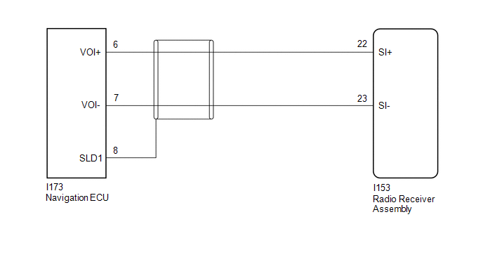
| 2. | CHECK HARNESS AND CONNECTOR (RADIO RECEIVER ASSEMBLY - NAVIGATION ECU) |
(a) Disconnect the I153 radio receiver assembly connector.
(b) Disconnect the I173 navigation ECU connector.
(c) Measure the resistance according to the value(s) in the table below.
Standard Resistance:
| Tester Connection | Condition | Specified Condition |
|---|---|---|
| I153-22 (SI+) - I173-6 (VOI+) | Always | Below 1 Ω |
| I153-23 (SI-) - I173-7 (VOI-) | Always | Below 1 Ω |
| I153-22 (SI+) or I173-6 (VOI+) - Body ground | Always | 10 kΩ or higher |
| I153-23 (SI-) or I173-7 (VOI-) - Body ground | Always | 10 kΩ or higher |
| I173-8 (SLD1) - Body ground | Always | 10 kΩ or higher |
| OK | | PROCEED TO NEXT SUSPECTED AREA SHOWN IN PROBLEM SYMPTOMS TABLE |
.gif)
| NG | | REPAIR OR REPLACE HARNESS OR CONNECTOR |
READ NEXT:
 Route cannot be Calculated
PROCEDURE 1. SET DESTINATION (a) Set another destination and check if the system can calculate the route correctly. OK: Route can be correctly calculated. OK NORMAL OPERATION NG
Voice is not Recognized
PROCEDURE 1. CHECK CONDITION (a) While paying attention to the condition of the spoken voice command, perform a voice recognition operation. OK: Voice command is recognized normally. HINT:
Cellular Phone Registration Failure
CAUTION / NOTICE / HINT NOTICE: When replacing the radio receiver assembly, always replace it with a new one. If a radio receiver assembly which was installed to another vehicle is used, the following
SEE MORE:
Drive Motor "A" Control Module (P0A1B-554,P0A1C-169)
DTC SUMMARY MALFUNCTION DESCRIPTION These DTCs indicate that a large current flowed in the boost converter. The cause of this malfunction may be one of the following: Internal inverter malfunction
Inverter internal circuit malfunction
Malfunction in ECU that controls the inverter
DESCRIPTION
System Information not Received (C13AE)
DESCRIPTION DTC No. Detection Item DTC Detection Condition Trouble Area Memory Note C13AE System Information not Received Both of following conditions are met:
Power switch is on (IG)
After parking brake ECU assembly is replaced, when power switch is first turned on (IG), s
