- DTC judgment completed
- System normal
Lexus NX: A/F Sensor Slow Response - Rich to Lean Bank 1 Sensor 1 (P014C,P014D,P015A,P015B)
Lexus NX Service Manual / Engine & Hybrid System / 2ar-fxe (engine Control) / Sfi System / A/F Sensor Slow Response - Rich to Lean Bank 1 Sensor 1 (P014C,P014D,P015A,P015B)
DESCRIPTION
Refer to DTC P2195.
Click here .gif)
| DTC No. | Detection Item | DTC Detection Condition | Trouble Area | MIL | Memory |
|---|---|---|---|---|---|
| P014C | A/F Sensor Slow Response - Rich to Lean Bank 1 Sensor 1 | The "Rich to Lean response rate deterioration level*" value is standard or less (2 trip detection logic). |
| Comes on | DTC stored |
| P014D | A/F Sensor Slow Response - Lean to Rich Bank 1 Sensor 1 | The "Lean to Rich response rate deterioration level*" value is standard or higher (2 trip detection logic). |
| Comes on | DTC stored |
| P015A | A/F Sensor Delayed Response - Rich to Lean Bank 1 Sensor 1 | The "Rich to Lean delay level*" value is standard or more (2 trip detection logic). |
| Comes on | DTC stored |
| P015B | A/F Sensor Delayed Response - Lean to Rich Bank 1 Sensor 1 | The "Lean to Rich delay level*" value is standard or more (2 trip detection logic). |
| Comes on | DTC stored |
*: Calculated by the ECM based on the air fuel ratio sensor output.
MONITOR DESCRIPTION
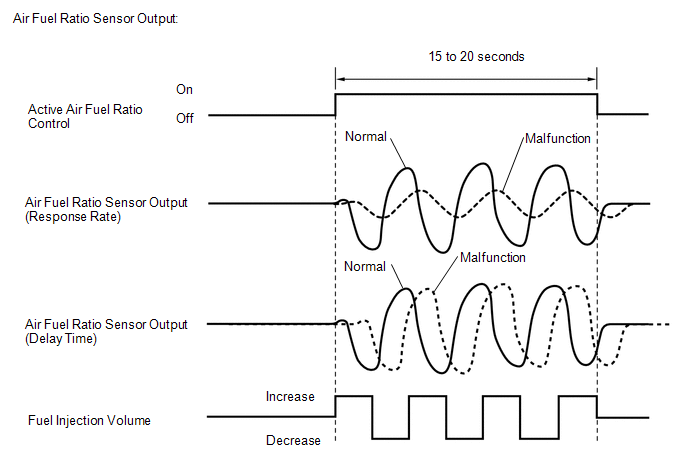
After the engine has been warmed up, the ECM carries out air fuel ratio feedback control and maintains the air fuel ratio at the stoichiometric level. In addition, after all the preconditions have been met, active air fuel ratio control is carried out for approximately 15 to 20 seconds, and during active air fuel ratio control, the ECM measures the response of the air fuel ratio sensor by increasing or decreasing the injection volume by a specific quantity based on the stoichiometric air fuel ratio learned during normal air fuel control. The ECM determines whether there is an air fuel ratio sensor malfunction at the mid-point of active air fuel ratio control.
If the air fuel ratio sensor's response ability is reduced, DTC P014C and P014D are stored.
If the time it takes the air fuel ratio sensor output to change is delayed, DTC P015A and P015B are stored.
MONITOR STRATEGY
| Related DTCs | P014C: Air fuel ratio sensor response rate (rich to lean response rate) P014D: Air fuel ratio sensor response rate (lean to rich response rate) P015A: Air fuel ratio sensor response rate (rich to lean delay) P015B: Air fuel ratio sensor response rate (lean to rich delay) |
| Required Sensors/Components (Main) | Air fuel ratio sensor |
| Required Sensors/Components (Related) | Crankshaft position sensor |
| Frequency of Operation | Once per driving cycle |
| Duration | 10 to 15 seconds |
| MIL Operation | 2 driving cycles |
| Sequence of Operation | None |
TYPICAL ENABLING CONDITIONS
| Monitor runs whenever the following DTCs are not stored | P0016 (VVT system - misalignment) P0031, P0032, P101D (Air fuel ratio sensor heater) P0102, P0103 (Mass air flow meter) P0107, P0108 (Manifold absolute pressure) P0112, P0113 (Intake air temperature sensor) P0115, P0117, P0118 (Engine coolant temperature sensor) P0120, P0121, P0122, P0123, P0220, P0222, P0223, P2135 (Throttle position sensor) P0125 (Insufficient coolant temperature for closed loop fuel control) P0128 (Thermostat) P0171, P0172 (Fuel system) P0300, P0301, P0302, P0303, P0304 (Misfire) P0335 (Crankshaft position sensor) P0340 (Camshaft position sensor) P0401 (EGR system) P0451, P0452, P0453 (EVAP system) P0505 (Idle speed control) P219A, P219C, P219D, P219E, P219F (Air-fuel ratio imbalance) |
| Active air fuel ratio control | Performing |
| Active air fuel ratio control is performed when the following conditions met | - |
| Auxiliary battery voltage | 11 V or higher |
| Engine coolant temperature | 73°C (163°F) or higher |
| Idle | Off |
| Engine speed | 1000 rpm or higher, and less than 4000 rpm |
| Air fuel ratio sensor status | Activated |
| Fuel-cut | Off |
| Engine load | 10% or higher, and less than 70% |
| Catalyst monitor | Not yet |
| Mass air flow | 4.5 gm/sec. or more, and less than 12.0 gm/sec. |
TYPICAL MALFUNCTION THRESHOLDS
P014C: Air Fuel Ratio Sensor Response Rate (Rich to Lean Response Rate)| Rich to Lean Response rate deterioration level | 0.04 V or less |
| Lean to Rich Response rate deterioration level | -0.041 V or higher |
| Rich to Lean delay level | 360 msec. or more |
| Lean to Rich delay level | 360 msec. or more |
MONITOR RESULT
Refer to detailed information in Checking Monitor Status.
Click here
| Monitor ID | Test ID | Scaling | Unit | Description |
|---|---|---|---|---|
| $01 | $93 | Multiply by 0.00012 | V | Rich to Lean response rate deterioration level |
| Monitor ID | Test ID | Scaling | Unit | Description |
|---|---|---|---|---|
| $01 | $94 | Multiply by 0.00012 | V | Lean to Rich response rate deterioration level |
| Monitor ID | Test ID | Scaling | Unit | Description |
|---|---|---|---|---|
| $01 | $95 | Multiply by 0.001 | Second | Rich to Lean delay level |
| Monitor ID | Test ID | Scaling | Unit | Description |
|---|---|---|---|---|
| $01 | $96 | Multiply by 0.001 | Second | Lean to Rich delay level |
CONFIRMATION DRIVING PATTERN
HINT:
Performing this confirmation pattern will activate the air fuel ratio sensor response monitor.
- Connect the Techstream to the DLC3.
- Turn the power switch on (IG).
- Turn the Techstream on.
- Clear the DTCs (even if no DTCs are stored, perform the clear DTC procedure).
- Turn the power switch off and wait for at least 30 seconds.
- Turn the power switch on (IG) and turn the Techstream on.
-
Put the engine in inspection mode (maintenance mode).
Click here
- Enter the following menus: Powertrain / Engine and ECT / Monitor / Current Monitor.
-
Check that O2 Sensor / Current is Incomplete.
HINT:
The test values for the test items RL RES RATE B1S1, LR RES RATE B1S1, RL DELAY B1S1 and LR DELAY B1S1 do not exist in the Detail of O2 Sensor monitor at this time (the initial value of "0.000" is indicated in each test item).
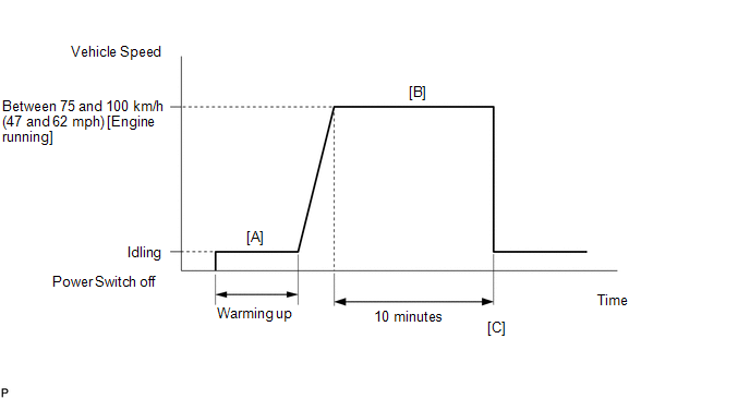
- Start the engine and warm it up (until the engine coolant temperature is 73°C (163°F) or higher) [A].
-
With the engine running, drive the vehicle at a constant speed between 75 and 100 km/h (47 and 62 mph) for 10 minutes [B].
CAUTION:
When performing the confirmation driving pattern, obey all speed limits and traffic laws.
HINT:
If the engine stops, further depress the accelerator pedal to restart the engine.
-
Check that O2 Sensor / Current becomes Complete.
HINT:
Check the test values on the Techstream by entering the following menus: Powertrain / Engine and ECT / Monitor / Current Monitor / O2 Sensor / Details / RL RES RATE B1S1, LR RES RATE B1S1, RL DELAY B1S1 and LR DELAY B1S1.
-
If the monitor item O2 Sensor / Current does not become Complete (if the test values indicated on the Techstream do not change), perform Readiness Monitor Drive Pattern for the air fuel ratio sensor and heated oxygen sensor.
Click here
- Enter the following menus: Powertrain / Engine and ECT / Trouble Codes [C].
-
Read the pending DTCs.
HINT:
- If a pending DTC is output, the system is malfunctioning.
- If a pending DTC is not output, perform the following procedure.
- Enter the following menus: Powertrain / Engine and ECT / Utility / All Readiness.
- Input the DTC: P014C, P014D, P015A or P015B.
-
Check the DTC judgment result.
Techstream Display
Description
NORMAL
ABNORMAL
- DTC judgment completed
- System abnormal
INCOMPLETE
- DTC judgment not completed
- Perform driving pattern after confirming DTC enabling conditions
N/A
- Unable to perform DTC judgment
- Number of DTCs which do not fulfill DTC preconditions has reached ECU memory limit
HINT:
- If the judgment result shows NORMAL, the system is normal.
- If the judgment result shows ABNORMAL, the system has a malfunction.
-
If the judgment result is INCOMPLETE or N/A and no pending DTC is output, perform a universal trip and check for permanent DTCs.
Click here
HINT:
- If a permanent DTC is output, the system is malfunctioning.
- If no permanent DTC is output, the system is normal.
WIRING DIAGRAM
Refer to DTC P2195.
Click here
CAUTION / NOTICE / HINT
NOTICE:
Inspect the fuses for circuits related to this system before performing the following procedure.
HINT:
- A low air fuel ratio sensor voltage could be caused by a rich air fuel mixture. Check for conditions that would cause the engine to run rich.
- A high air fuel ratio sensor voltage could be caused by a lean air fuel mixture. Check for conditions that would cause the engine to run lean.
- Sensor 1 refers to the sensor closest to the engine assembly.
- Sensor 2 refers to the sensor farthest away from the engine assembly.
- Read freeze frame data using the Techstream. The ECM records vehicle and driving condition information as freeze frame data the moment a DTC is stored. When troubleshooting, freeze frame data can be helpful in determining whether the vehicle was moving or stationary, whether the engine was warmed up or not, whether the air fuel ratio was lean or rich, as well as other data recorded at the time of a malfunction.
PROCEDURE
| 1. | CHECK ANY OTHER DTCS OUTPUT (IN ADDITION TO DTC P014C, P014D, P015A OR P015B) |
(a) Connect the Techstream to the DLC3.
(b) Turn the power switch on (IG).
(c) Turn the Techstream on.
(d) Enter the following menus: Powertrain / Engine and ECT / Trouble Codes.
(e) Read the DTCs.
Powertrain > Engine and ECT > Trouble Codes| Result | Proceed to |
|---|---|
| DTC P014C, P014D, P015A or P015B is output | A |
| DTC P014C, P014D, P015A or P015B and other DTCs are output | B |
HINT:
If any DTCs other than P014C, P014D, P015A or P015B are output, troubleshoot those DTCs first.
| B | .gif) | GO TO DTC CHART |
|
.gif)
| 2. | INSPECT AIR FUEL RATIO SENSOR (HEATER RESISTANCE) |
Click here
| NG | | REPLACE AIR FUEL RATIO SENSOR |
|
| 3. | CHECK HARNESS AND CONNECTOR (AIR FUEL RATIO SENSOR - ECM) |
Click here
| NG | | REPAIR OR REPLACE HARNESS OR CONNECTOR |
|
| 4. | CHECK AIR FUEL RATIO SENSOR |
(a) Check that the proper air fuel ratio sensor is installed to the vehicle.
HINT:
Perform "Inspection After Repair" after replacing the air fuel ratio sensor.
Click here
| NG | | REPLACE AIR FUEL RATIO SENSOR |
|
| 5. | PERFORM CONFIRMATION DRIVING PATTERN |
(a) Drive the vehicle according to Confirmation Driving Pattern.
|
| 6. | CHECK WHETHER DTC OUTPUT RECURS (DTC P014C, P014D, P015A OR P015B) |
(a) Connect the Techstream to the DLC3.
(b) Turn the power switch on (IG).
(c) Turn the Techstream on.
(d) Enter the following menus: Powertrain / Engine and ECT / Trouble Codes / Pending.
(e) Read the pending DTCs.
Powertrain > Engine and ECT > Trouble Codes| Result | Proceed to |
|---|---|
| DTC P014C, P014D, P015A or P015B is output | A |
| DTCs are not output | B |
| B | | CHECK FOR INTERMITTENT PROBLEMS |
|
| 7. | REPLACE AIR FUEL RATIO SENSOR |
(a) Replace the air fuel ratio sensor.
Click here
HINT:
Perform "Inspection After Repair" after replacing the air fuel ratio sensor.
Click here
|
| 8. | PERFORM CONFIRMATION DRIVING PATTERN |
(a) Drive the vehicle according to Confirmation Driving Pattern.
|
| 9. | CHECK WHETHER DTC OUTPUT RECURS (DTC P014C, P014D, P015A OR P015B) |
(a) Connect the Techstream to the DLC3.
(b) Turn the power switch on (IG).
(c) Turn the Techstream on.
(d) Enter the following menus: Powertrain / Engine and ECT / Trouble Codes / Pending.
(e) Read the pending DTCs.
Powertrain > Engine and ECT > Trouble Codes| Result | Proceed to |
|---|---|
| DTCs are not output | A |
| DTC P014C, P014D, P015A or P015B is output | B |
| A | | END |
| B | | CHECK ENGINE TO DETERMINE CAUSE OF EXTREMELY RICH OR LEAN ACTUAL AIR FUEL RATIO |
READ NEXT:
 System Too Lean (Bank 1) (P0171,P0172)
DESCRIPTION The fuel trim is related to the feedback compensation value, not to the basic injection duration. The fuel trim consists of both the short-term and long-term fuel trims. The short-term fue
Random / Multiple Cylinder Misfire Detected (P0300-P0304)
DESCRIPTION When the engine misfires, high concentrations of hydrocarbons (HC) enter the exhaust gas. Extremely high hydrocarbon concentration levels can cause an increase in exhaust emission levels.
Knock Sensor 1 Circuit Low Input (Bank 1 or Single Sensor) (P0327,P0328)
DESCRIPTION A flat type knock control sensor (non-resonant type) has a structure that can detect vibration between approximately 5 kHz and 23 kHz. The knock control sensors are fitted onto the engine
SEE MORE:
Inspection
INSPECTION PROCEDURE 1. INSPECT SHIFT LEVER POSITION SENSOR (a) Measure the resistance according to the value(s) in the table below. Standard Resistance: Tester Connection Condition Specified Condition 7 (+B) - 3 (PR) Shift lever in P Below 1 Ω 7 (+B) - 4 (PNB) Below 1 Ω
Removal
REMOVAL PROCEDURE 1. REMOVE BACK DOOR CENTER GARNISH Click here 2. REMOVE BACK DOOR SIDE GARNISH LH Click here 3. REMOVE BACK DOOR SIDE GARNISH RH Click here 4. REMOVE BACK DOOR TRIM BASE Click here 5. REMOVE PULL HANDLE Click here 6. REMOVE BACK DOOR LOCK COVER Click here 7. REMOV
© 2016-2024 Copyright www.lexunx.com
