Lexus NX: Abnormal Power Supply Voltage in Yaw Rate and/or Deceleration Sensor (C1381)
DESCRIPTION
This DTC is stored when the skid control ECU (brake booster with master cylinder assembly) receives a sensor supply voltage malfunction signal from the yaw rate and acceleration sensor (airbag ECU assembly). This DTC may also be stored due to a temporary power source voltage drop.
| DTC No. | Detection Item | INF Code | DTC Detection Condition | Trouble Area | Note |
|---|---|---|---|---|---|
| C1381 | Abnormal Power Supply Voltage in Yaw Rate and/or Deceleration Sensor | 601 | While acceleration sensor communication is enabled, a supply voltage malfunction signal is received from the sensor for 10 seconds. |
| - |
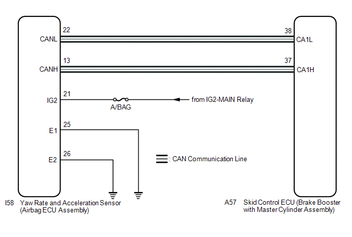
WIRING DIAGRAM
CAUTION / NOTICE / HINT
NOTICE:
-
When replacing the yaw rate and acceleration sensor (airbag ECU assembly), perform zero point calibration.
Click here
.gif)
- Inspect the fuses for circuits related to this system before performing the following inspection procedure.
PROCEDURE
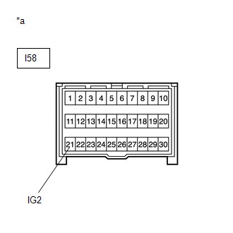
| 1. | CHECK HARNESS AND CONNECTOR (IG2 TERMINAL) |
NOTICE:
-
After the power switch is turned off, there may be a waiting time before disconnecting the negative (-) auxiliary battery terminal.
Click here
-
When disconnecting and reconnecting the auxiliary battery
Click here
HINT:
When disconnecting and reconnecting the auxiliary battery, there is an automatic learning function that completes learning when the respective system is used.
Click here
(a) Turn the power switch off.
(b) Disconnect the cable from the negative (-) auxiliary battery terminal, and wait for at least 90 seconds.
| (c) Make sure that there is no looseness at the locking part and the connecting part of the connector. |
|
(d) Disconnect the I58 yaw rate and acceleration sensor (airbag ECU assembly) connector.
(e) Connect the cable to the negative (-) auxiliary battery terminal, and wait for at least 2 seconds.
(f) Turn the power switch on (IG).
(g) Operate all the components of the electrical system (defogger, wipers, headlights, heater blower, etc.).
(h) Measure the voltage according to the value(s) in the table below.
Standard Voltage:
| Tester Connection | Switch Condition | Specified Condition |
|---|---|---|
| I58-21 (IG2) - Body ground | Power switch on (IG) | 11 to 14 V |
| NG | .gif) | REPAIR OR REPLACE HARNESS OR CONNECTOR (IG2 CIRCUIT) |
|
.gif)
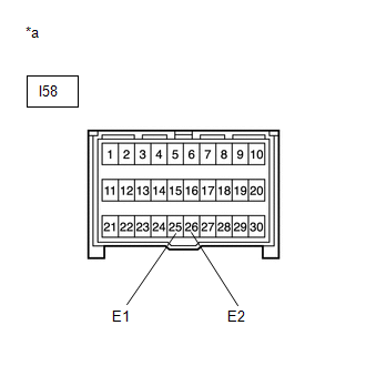
| 2. | CHECK HARNESS AND CONNECTOR (E TERMINAL) |
| (a) Turn the power switch off. |
|
(b) Measure the resistance according to the value(s) in the table below.
Standard Resistance:
| Tester Connection | Condition | Specified Condition |
|---|---|---|
| I58-25 (E1) - Body ground | Always | Below 1 Ω |
| I58-26 (E2) - Body ground | Always | Below 1 Ω |
NOTICE:
Check the yaw rate and acceleration sensor signal after replacement.
Click here
HINT:
If troubleshooting has been carried out according to Problem Symptoms Table, refer back to the table and proceed to the next step.
Click here
| NG | | REPAIR OR REPLACE HARNESS OR CONNECTOR (E CIRCUIT) |
|
| 3. | RECONFIRM DTC |
(a) Reconnect the I58 yaw rate and acceleration sensor (airbag ECU assembly) connector.
(b) Clear the DTC.
Click here
(c) Turn the power switch off.
(d) Turn the power switch on (READY).
(e) Perform a road test.
(f) Check if the same DTC is recorded.
Click here
| Result | Proceed to |
|---|---|
| DTC C1381 is not output | A |
| DTC C1381 is output | B |
NOTICE:
Check the yaw rate and acceleration sensor signal after replacement.
Click here
HINT:
If troubleshooting has been carried out according to Problem Symptoms Table, refer back to the table and proceed to the next step.
Click here
| A | | USE SIMULATION METHOD TO CHECK |
| B | | REPLACE AIRBAG ECU ASSEMBLY |
READ NEXT:
 Abnormal Leak in Accumulator (C1391)
DESCRIPTION This DTC is stored if internal or external brake fluid leaks are detected due to improper sealing in the brake actuator (brake booster with master cylinder assembly) or brake booster pump
EPB System Malfunction (C13AF)
DESCRIPTION The skid control ECU (brake booster with master cylinder assembly) is connected to the parking brake ECU assembly via CAN communication. If an electric parking brake system malfunction occ
Steering Angle Sensor Initialization Incomplete (C1439,C1445)
DESCRIPTION The skid control ECU (brake booster with master cylinder assembly) acquires the steering sensor zero point every time the power switch is turned on (IG) and the vehicle is driven at 35 km/
SEE MORE:
ECM / PCM Processor (P0606)
MONITOR DESCRIPTION The ECM continuously monitors its main and sub CPUs. This self-check ensures that the ECM is functioning properly. If outputs from these CPUs are different and deviate from the standard, the ECM will illuminate the MIL and store this DTC. DTC No. Detection Item DTC Detecti
Driver Side Door Entry Lock and Unlock Functions do not Operate
DESCRIPTION If the entry lock and unlock functions do not operate for the driver door only, the request code may not be being transmitted from the driver door or the front door outside handle assembly (for driver door) (touch sensor) may be malfunctioning. If the entry functions for other doors oper
