Lexus NX: Foreign Object is Attached on Tip of Front Speed Sensor RH (C1235,C1236,C1238,C1239,C1275-C1278)
DESCRIPTION
When foreign matter adheres to a speed sensor tip or speed sensor rotor, these DTCs are stored. The presence of foreign matter can be judged when an abnormal waveform is received from a sensor.
These DTCs may also be detected when a malfunction occurs in the connector terminals or wire harness of the speed sensor circuit.
DTCs C1275 to C1278 will be cleared when the speed sensor sends a wheel speed signal or when Test Mode ends. DTCs from C1275 to C1278 are output only in Test Mode.
| DTC No. | Detection Item | INF Code | DTC Detection Condition | Trouble Area | Note |
|---|---|---|---|---|---|
| C1235 | Foreign Object is Attached on Tip of Front Speed Sensor RH | 541 | Either of the following is detected:
|
| - |
| C1236 | Foreign Object is Attached on Tip of Front Speed Sensor LH | 542 | Either of the following is detected:
|
| - |
| C1238 | Foreign Object is Attached on Tip of Rear Speed Sensor RH | 543 | Either of the following is detected:
|
| - |
| C1239 | Foreign Object is Attached on Tip of Rear Speed Sensor LH | 544 | Either of the following is detected:
|
| - |
| C1275 | Abnormal Change in Output Signal of Front Speed Sensor RH | - | Detected only during Test Mode. |
| - |
| C1276 | Abnormal Change in Output Signal of Front Speed Sensor LH | - | Detected only during Test Mode. |
| - |
| C1277 | Abnormal Change in Output Signal of Rear Speed Sensor RH | - | Detected only during Test Mode. |
| - |
| C1278 | Abnormal Change in Output Signal of Rear Speed Sensor LH | - | Detected only during Test Mode. |
| - |
WIRING DIAGRAM
Refer to DTCs C1464, C1465, C1466 and C1467.
for Front: Click here .gif)
for Rear: Click here
CAUTION / NOTICE / HINT
NOTICE:
When replacing the skid control ECU (brake booster with master cylinder assembly), perform initialization and calibration of the linear solenoid valve.
Click here
PROCEDURE
| 1. | CHECK DTC |
(a) Check that no speed sensor malfunction DTCs are output.
Click here
HINT:
When C1464, C1465, C1466, and/or C1467 are output together with C1235, C1236, C1238, and/or C1239, inspect and repair the trouble areas indicated by C1464, C1465, C1466, and/or C1467 first.
| Result | Proceed to |
|---|---|
| DTCs C1235 and/or C1236 are output. | A |
| DTCs C1238 and C1239 are output. | B |
| Speed sensor malfunction DTCs (C1464, C1465, C1466 and/or C1467) are output. | C |
| B | .gif) | GO TO STEP 13 |
| C | | REPAIR CIRCUITS INDICATED BY OUTPUT DTCS |
|
.gif)
| 2. | CHECK FRONT SPEED SENSOR AND SENSOR ROTOR |
(a) Remove the front speed sensor and the component with the sensor rotor.
for Speed Sensor: Click here
for Speed Sensor Rotor: Click here
(b) Check the speed sensor tip and speed sensor rotor.
OK:
The sensor tip and rotor are free of scratches, oil, and foreign matter.
NOTICE:
-
If no damage to the speed sensor tip is found during this inspection, do not replace the speed sensor.
If there are any ferrous metal filings stuck to the rotor, this will result in a malfunction, so confirm that the rotor is not contaminated with foreign matter before replacing the sensor.
-
Check the speed sensor signal after cleaning or replacement.
Click here
| OK (w/ AVS) | | GO TO STEP 10 |
| NG | | CLEAN OR REPLACE FRONT SPEED SENSOR OR COMPONENT WITH SENSOR ROTOR |
|
| 3. | CHECK HARNESS AND CONNECTOR (BRAKE BOOSTER WITH MASTER CYLINDER ASSEMBLY - FRONT SPEED SENSOR) |
(a) Install the front speed sensor and the component with the sensor rotor.
for Speed Sensor: Click here
for Speed Sensor Rotor: Click here
(b) Make sure that there is no looseness at the locking part and the connecting part of the connectors.
(c) Disconnect the A57 skid control ECU (brake booster with master cylinder assembly) connector.
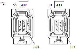
(d) Disconnect the A12 or A13 front speed sensor connector.
(e) Measure the resistance according to the value(s) in the table below.
Standard Resistance:
for RH| Tester Connection | Condition | Specified Condition |
|---|---|---|
| A57-18 (FR+) - A12-6 (FR+) | Always | Below 1 Ω |
| A57-18 (FR+) or A12-6 (FR+) - Body ground | Always | 10 kΩ or higher |
| A57-5 (FR-) - A12-5 (FR-) | Always | Below 1 Ω |
| A57-5 (FR-) or A12-5 (FR-) - Body ground | Always | 10 kΩ or higher |
| Tester Connection | Condition | Specified Condition |
|---|---|---|
| A57-31 (FL+) - A13-6 (FL+) | Always | Below 1 Ω |
| A57-31 (FL+) or A13-6 (FL+) - Body ground | Always | 10 kΩ or higher |
| A57-32 (FL-) - A13-5 (FL-) | Always | Below 1 Ω |
| A57-32 (FL-) or A13-5 (FL-) - Body ground | Always | 10 kΩ or higher |
| NG | | REPAIR OR REPLACE HARNESS OR CONNECTOR |
|
| 4. | INSPECT BRAKE BOOSTER WITH MASTER CYLINDER ASSEMBLY (SENSOR OUTPUT) |
| (a) Reconnect the A57 skid control ECU (brake booster with master cylinder assembly) connector. |
|
(b) Turn the power switch on (IG).
(c) Measure the voltage according to the value(s) in the table below.
Standard Voltage:
for RH| Tester Connection | Switch Condition | Specified Condition |
|---|---|---|
| A12-6 (FR+) - Body ground | Power switch on (IG) | 5.7 to 14 V |
| Tester Connection | Switch Condition | Specified Condition |
|---|---|---|
| A13-6 (FL+) - Body ground | Power switch on (IG) | 5.7 to 14 V |
| NG | | REPLACE BRAKE BOOSTER WITH MASTER CYLINDER ASSEMBLY |
|
| 5. | RECONFIRM DTC |
(a) Turn the power switch off.
(b) w/o AVS
Reconnect the A12 or A13 front speed sensor connector.
(c) w/ AVS
Reconnect the A or B front skid control sensor wire connector.
(d) Clear the DTCs.
Click here
(e) Turn the power switch on (READY).
(f) Drive the vehicle at a speed of 20 km/h (12 mph) or more for at least 15 seconds.
(g) Check if the same DTC is output.
Click here
| Result | Proceed to |
|---|---|
| DTCs C1235 and/or C1236 are output. | A |
| DTCs C1235 and C1236 are not output. | B |
| B | | USE SIMULATION METHOD TO CHECK |
|
| 6. | REPLACE FRONT SPEED SENSOR |
(a) Turn the power switch off.
(b) Replace the front speed sensor.
Click here
NOTICE:
Check the speed sensor signal after replacement.
Click here
|
| 7. | RECONFIRM DTC |
(a) Clear the DTCs.
Click here
(b) Turn the power switch on (READY).
(c) Drive the vehicle at a speed of 20 km/h (12 mph) or more for at least 15 seconds.
(d) Check if the same DTC is output.
Click here
| Result | Proceed to |
|---|---|
| DTCs C1235 and/or C1236 are output. | A |
| DTCs C1235 and C1236 are not output. | B |
| B | | END |
|
| 8. | REPLACE FRONT AXLE HUB SUB-ASSEMBLY |
(a) Turn the power switch off.
(b) Replace the front speed sensor rotor (front axle hub sub-assembly).
Click here
HINT:
The front speed sensor rotor is incorporated into the front axle hub sub-assembly.
If the front speed sensor rotor needs to be replaced, replace the front axle hub sub-assembly.
NOTICE:
Check the speed sensor signal after replacement.
Click here
|
| 9. | RECONFIRM DTC |
(a) Clear the DTCs.
Click here
(b) Turn the power switch on (READY).
(c) Drive the vehicle at a speed of 20 km/h (12 mph) or more for at least 15 seconds.
(d) Check if the same DTC is output.
Click here
| Result | Proceed to |
|---|---|
| DTCs C1235 and/or C1236 are output. | A |
| DTCs C1235 and C1236 are not output. | B |
| A | | REPLACE BRAKE BOOSTER WITH MASTER CYLINDER ASSEMBLY |
| B | | END |
| 10. | INSPECT FRONT SKID CONTROL SENSOR WIRE |
(a) Install the front speed sensor and the component with the sensor rotor.
for Speed Sensor: Click here
for Speed Sensor Rotor: Click here
(b) Make sure that there is no looseness at the locking part and the connecting part of the connectors.
(c) Disconnect the A75 or A76 front skid control sensor wire connector.
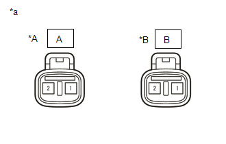
(d) Disconnect the A or B front skid control sensor wire connector.
(e) Measure the resistance according to the value(s) in the table below.
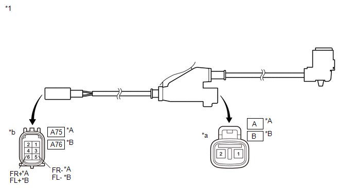
| *A | for RH | *B | for LH |
| *1 | Front Skid Control Sensor Wire | - | - |
| *a | Front view of wire harness connector (to Front Speed Sensor Side Connector) | *b | Front view of wire harness connector (to Vehicle Side Connector) |
Standard Resistance:
for RH| Tester Connection | Condition | Specified Condition |
|---|---|---|
| A-1 - A75-6 (FR+) | Always | Below 1 Ω |
| A-1 or A75-6 (FR+) - Body ground and other terminals | Always | 10 kΩ or higher |
| A-2 - A75-5 (FR-) | Always | Below 1 Ω |
| A-2 or A75-5 (FR-) - Body ground and other terminals | Always | 10 kΩ or higher |
| Tester Connection | Condition | Specified Condition |
|---|---|---|
| B-1 - A76-6 (FL+) | Always | Below 1 Ω |
| B-1 or A76-6 (FL+) - Body ground and other terminals | Always | 10 kΩ or higher |
| B-2 - A76-5 (FL-) | Always | Below 1 Ω |
| B-2 or A76-5 (FL-) - Body ground and other terminals | Always | 10 kΩ or higher |
| NG | | REPLACE FRONT SKID CONTROL SENSOR WIRE |
|
| 11. | CHECK HARNESS AND CONNECTOR (BRAKE BOOSTER WITH MASTER CYLINDER ASSEMBLY - FRONT SPEED SENSOR) |
(a) Make sure that there is no looseness at the locking part and the connecting part of the connectors.
(b) Reconnect the A75 or A76 front skid control sensor wire connector.
(c) Disconnect the A57 skid control ECU (brake booster with master cylinder assembly) connector.
(d) Measure the resistance according to the value(s) in the table below.
Standard Resistance:
for RH| Tester Connection | Condition | Specified Condition |
|---|---|---|
| A57-18 (FR+) - A-1 | Always | Below 1 Ω |
| A57-18 (FR+) or A-1 - Body ground | Always | 10 kΩ or higher |
| A57-5 (FR-) - A-2 | Always | Below 1 Ω |
| A57-5 (FR-) or A-2 - Body ground | Always | 10 kΩ or higher |
| Tester Connection | Condition | Specified Condition |
|---|---|---|
| A57-31 (FL+) - B-1 | Always | Below 1 Ω |
| A57-31 (FL+) or B-1 - Body ground | Always | 10 kΩ or higher |
| A57-32 (FL-) - B-2 | Always | Below 1 Ω |
| A57-32 (FL-) or B-2 - Body ground | Always | 10 kΩ or higher |
| NG | | REPAIR OR REPLACE HARNESS OR CONNECTOR |
|
| 12. | INSPECT BRAKE BOOSTER WITH MASTER CYLINDER ASSEMBLY (SENSOR OUTPUT) |
| (a) Reconnect the A57 skid control ECU (brake booster with master cylinder assembly) connector. |
|
(b) Turn the power switch on (IG).
(c) Measure the voltage according to the value(s) in the table below.
Standard Voltage:
for RH| Tester Connection | Switch Condition | Specified Condition |
|---|---|---|
| A-1 - Body ground | Power switch on (IG) | 5.7 to 14 V |
| Tester Connection | Switch Condition | Specified Condition |
|---|---|---|
| B-1- Body ground | Power switch on (IG) | 5.7 to 14 V |
| OK | | GO TO STEP 5 |
| NG | | REPLACE BRAKE BOOSTER WITH MASTER CYLINDER ASSEMBLY |
| 13. | CHECK REAR SPEED SENSOR AND SENSOR ROTOR |
(a) Remove the rear speed sensor and the component with the sensor rotor.
for Speed Sensor: Click here
for Speed Sensor Rotor: Click here
(b) Check the speed sensor tip and speed sensor rotor.
OK:
The sensor tip and rotor are free of scratches, oil, and foreign matter.
NOTICE:
-
If no damage to the speed sensor tip is found during this inspection, do not replace the speed sensor.
If there are any ferrous metal filings stuck to the rotor, this will result in a malfunction, so confirm that the rotor is not contaminated with foreign matter before replacing the sensor.
-
Check the speed sensor signal after cleaning or replacement.
Click here
| NG | | CLEAN OR REPLACE REAR SPEED SENSOR OR COMPONENT WITH SENSOR ROTOR |
|
| 14. | CHECK HARNESS AND CONNECTOR (BRAKE BOOSTER WITH MASTER CYLINDER ASSEMBLY - REAR SPEED SENSOR) |
(a) Install the rear speed sensor and the component with the sensor rotor.
for Speed Sensor: Click here
for Speed Sensor Rotor: Click here
(b) Make sure that there is no looseness at the locking part and the connecting part of the connectors.
(c) Disconnect the A57 skid control ECU (brake booster with master cylinder assembly) connector.
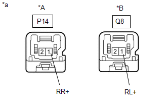
(d) Disconnect the P14 or Q8 rear speed sensor connector.
(e) Measure the resistance according to the value(s) in the table below.
Standard Resistance:
for RH| Tester Connection | Condition | Specified Condition |
|---|---|---|
| A57-22 (RR+) - P14-1 (RR+) | Always | Below 1 Ω |
| A57-22 (RR+) or P14-1 (RR+) - Body ground | Always | 10 kΩ or higher |
| A57-9 (RR-) - P14-2 (RR-) | Always | Below 1 Ω |
| A57-9 (RR-) or P14-2 (RR-) - Body ground | Always | 10 kΩ or higher |
| Tester Connection | Condition | Specified Condition |
|---|---|---|
| A57-20 (RL+) - Q8-1 (RL+) | Always | Below 1 Ω |
| A57-20 (RL+) or Q8-1 (RL+) - Body ground | Always | 10 kΩ or higher |
| A57-7 (RL-) - Q8-2 (RL-) | Always | Below 1 Ω |
| A57-7 (RL-) or Q8-2 (RL-) - Body ground | Always | 10 kΩ or higher |
| NG | | REPAIR OR REPLACE HARNESS OR CONNECTOR |
|
| 15. | INSPECT BRAKE BOOSTER WITH MASTER CYLINDER ASSEMBLY (SENSOR OUTPUT) |
| (a) Reconnect the A57 skid control ECU (brake booster with master cylinder assembly) connector. |
|
(b) Turn the power switch on (IG).
(c) Measure the voltage according to the value(s) in the table below.
Standard Voltage:
for RH| Tester Connection | Switch Condition | Specified Condition |
|---|---|---|
| P14-1 (RR+) - Body ground | Power switch on (IG) | 5.7 to 14 V |
| Tester Connection | Switch Condition | Specified Condition |
|---|---|---|
| Q8-1 (RL+) - Body ground | Power switch on (IG) | 5.7 to 14 V |
| NG | | REPLACE BRAKE BOOSTER WITH MASTER CYLINDER ASSEMBLY |
|
| 16. | RECONFIRM DTC |
(a) Turn the power switch off.
(b) Reconnect the P14 or Q8 rear speed sensor connector.
(c) Clear the DTCs.
Click here
(d) Turn the power switch on (READY).
(e) Drive the vehicle at a speed of 20 km/h (12 mph) or more for at least 15 seconds.
(f) Check if the same DTC is output.
Click here
| Result | Proceed to |
|---|---|
| DTCs C1238 and/or C1239 are output. | A |
| DTCs C1238 and C1239 are not output. | B |
| B | | USE SIMULATION METHOD TO CHECK |
|
| 17. | REPLACE REAR SPEED SENSOR |
(a) Turn the power switch off.
(b) Replace the rear speed sensor.
Click here
NOTICE:
Check the speed sensor signal after replacement.
Click here
|
| 18. | RECONFIRM DTC |
(a) Clear the DTCs.
Click here
(b) Turn the power switch on (READY).
(c) Drive the vehicle at a speed of 20 km/h (12 mph) or more for at least 15 seconds.
(d) Check if the same DTC is output.
Click here
| Result | Proceed to |
|---|---|
| DTCs C1238 and/or C1239 are output. | A |
| DTCs C1238 and C1239 are not output. | B |
| B | | END |
|
| 19. | REPLACE REAR AXLE HUB AND BEARING ASSEMBLY |
(a) Turn the power switch off.
(b) Replace the rear speed sensor rotor (rear axle hub and bearing assembly).
Click here
HINT:
The rear speed sensor rotor is incorporated into the rear axle hub and bearing assembly.
If the rear speed sensor rotor needs to be replaced, replace the rear axle hub and bearing assembly.
NOTICE:
Check the speed sensor signal after replacement.
Click here
|
| 20. | RECONFIRM DTC |
(a) Clear the DTCs.
Click here
(b) Turn the power switch on (READY).
(c) Drive the vehicle at a speed of 20 km/h (12 mph) or more for at least 15 seconds.
(d) Check if the same DTC is output.
Click here
| Result | Proceed to |
|---|---|
| DTCs C1238 and/or C1239 are output. | A |
| DTCs C1238 and C1239 are not output. | B |
| A | | REPLACE BRAKE BOOSTER WITH MASTER CYLINDER ASSEMBLY |
| B | | END |
READ NEXT:
 Low or High Power Supply Voltage (C1241,C1242)
DESCRIPTION If a malfunction is detected in the power supply circuit, the skid control ECU (brake booster with master cylinder assembly) power source voltage drops, or there is insufficient voltage to
Master Cylinder Pressure Sensor (C1246,C1281,C1364)
DESCRIPTION The regulator pressure sensor and wheel cylinder pressure sensor are built into the brake actuator. They measure their respective pressures and send signals to the skid control ECU (brake
Stroke Sensor (C1247,C1346,C1392)
DESCRIPTION The brake pedal stroke sensor assembly sends a signal about the pedal stroke to the skid control ECU (brake booster with master cylinder assembly). DTC C1346 will be cleared when the brake
SEE MORE:
LED Headlight LH Circuit Malfunction (B2430,B2431)
DESCRIPTION The illumination of the low beam headlights is controlled by the main body ECU (multiplex network body ECU). When the headlights are turned on, the main body ECU (multiplex network body ECU) receives a signal from the headlight assembly and detects the illumination condition of the low b
Side Camera Feedback Malfunction (C1683)
DESCRIPTION This DTC is stored if the parking assist ECU judges as a result of its self check that a synchronization problem is occurring in the image signal sent from the passenger side television camera assembly to the parking assist ECU. DTC No. Detection Item DTC Detection Condition Tro
