Lexus NX: Hybrid Battery Voltage System Isolation Fault (P0AA6-611)
DESCRIPTION
This DTC is stored if there is insulation malfunction in the high-voltage circuit in the air conditioning system. Possible causes are poor insulation in the compressor with motor assembly, or mixing of any oil other than ND-OIL 11 in the refrigerant cycle.
A high-voltage motor is built into the compressor with motor assembly and is cooled directly with refrigerant. Compressor oil (ND-OIL 11) with high insulation performance is used because a leakage of electrical power may occur if regular compressor oil (ND-OIL 8) is used.
CAUTION:
- Wear insulated gloves and pull out the service plug grip before inspection as procedures may require disconnecting high-voltage connectors. Carry the removed service plug in your pocket to prevent other technicians from accidentally reconnecting it while you are servicing the vehicle.
- Do not touch the high-voltage connectors or terminals for 10 minutes after the service plug grip is removed.
| DTC No. | Detection Item | DTC Detection Condition | Trouble Area | Memory | Note |
|---|---|---|---|---|---|
| P0AA6-611 | Hybrid Battery Voltage System Isolation Fault | High voltage system insulation malfunction |
| Memorized | - |
WIRING DIAGRAM
.png)
CAUTION / NOTICE / HINT
CAUTION:
- Wear insulated gloves and pull out the service plug grip before inspection as procedures may require disconnecting high-voltage connectors. Carry the removed service plug in your pocket to prevent other technicians from accidentally reconnecting it while you are servicing the vehicle.
- Do not touch the high-voltage connectors or terminals for 10 minutes after the service plug grip is removed.
NOTICE:
-
After the power switch is turned off, there may be a waiting time before disconnecting the negative (-) auxiliary battery terminal.
Click here
.gif)
-
When disconnecting and reconnecting the auxiliary battery terminal
Click here
HINT:
When disconnecting and reconnecting the auxiliary battery, there is an automatic learning function that completes learning when the respective system is used.
Click here
- Electrical insulation performance may decrease significantly if even a small amount of oil other than ND-OIL 11 is used (or enters) in the refrigerant cycle, causing a DTC to be output.
- If other oil is accidentally used and a DTC is output, collect as much oil in the refrigerant cycle into the compressor with motor assembly as possible and replace it with ND-OIL 11 to increase the ND-OIL 11 ratio amount.
- Replace the main components of the air conditioning cycle (evaporator, condenser, and compressor) if a large amount of oil other than ND-OIL 11 enters the system. Failing to do so may cause electrical insulation performance to remain low, causing a DTC to be output.
- The hybrid control system and air conditioning system output DTCs separately. Perform troubleshooting for the hybrid control system first if DTCs from these systems are output simultaneously.
HINT:
If it can be confirmed that any compressor oil other than ND-OIL 11 has been used in the vehicle, replace the main components of the air conditioning cycle.
PROCEDURE
| 1. | CHECK CAN COMMUNICATION SYSTEM |
(a) Using the Techstream, check if the CAN communication system is functioning normally.
Click here
| Result | Proceed to |
|---|---|
| CAN communication system DTCs are not output | A |
| CAN communication system DTCs are output | B |
| B | .gif) | GO TO CAN COMMUNICATION SYSTEM |
|
.gif)
| 2. | INSPECT COMPRESSOR WITH MOTOR ASSEMBLY |
CAUTION:
Because the compressor with motor assembly has a high-voltage circuit, wear insulated gloves and pull out the service plug grip to cut off the high-voltage circuit before inspection.
(a) Clear the DTCs.
Click here
(b) Turn the power switch on (READY).
(c) Prepare the vehicle according to the table below for 3 minutes.
| Item | Condition |
|---|---|
| Blower speed | HI |
| Temperature setting | MAX COLD |
| A/C switch | On |
(d) Turn the power switch off.
(e) Remove the service plug grip.
Click here
CAUTION:
Do not touch the high-voltage connectors or terminals for 10 minutes after the service plug grip is removed.
NOTICE:
After removing the service plug grip, turning the power switch on (READY) may cause a malfunction. Do not turn the power switch on (READY) with the service plug grip removed.
| (f) Disconnect the compressor with motor assembly connector. NOTICE: Do not allow any foreign matter or water to enter the compressor with motor assembly. |
|
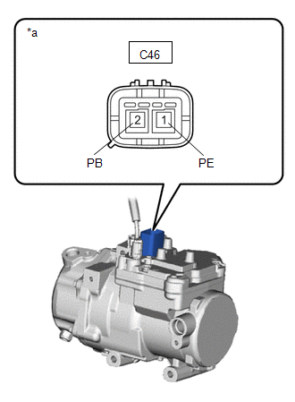
(g) Using a megohmmeter, measure the resistance according to the value(s) in the table below.
Standard Resistance:
| Tester Connection | Condition | Specified Condition |
|---|---|---|
| C46-1 (PE) - Body ground | Always | 2 MΩ or higher |
| C46-2 (PB) - Body ground | Always | 2 MΩ or higher |
| NG | | REPLACE COMPRESSOR WITH MOTOR ASSEMBLY |
|
| 3. | INSPECT AIR CONDITIONING CYCLE |
CAUTION:
Because the compressor with motor assembly has a high-voltage circuit, wear insulated gloves and pull out the service plug grip to cut off the high-voltage circuit before inspection.
(a) Reconnect the C46 the compressor with motor assembly connector.
(b) Install the service plug grip.
Click here
(c) Turn the power switch on (READY).
(d) Set the A/C temperature to 25°C (77°F) and blower switch to LO and then operate the compressor with motor assembly for 10 minutes to circulate the refrigerant and collect as much compressor oil as possible in the compressor with motor assembly.
(e) Turn the power switch off.
(f) Using a spot cooler or other tool, cool down the compressor with motor assembly for 30 minutes, or leave the vehicle overnight before inspection.
NOTICE:
Do not operate the compressor before inspection.
(g) Remove the service plug grip.
Click here
CAUTION:
Do not touch the high-voltage connectors or terminals for 10 minutes after the service plug grip is removed.
NOTICE:
After removing the service plug grip, turning the power switch on (READY) may cause a malfunction. Do not turn the power switch on (READY) with the service plug grip removed.
| (h) Disconnect the compressor with motor assembly connector. NOTICE: Do not allow any foreign matter or water to enter the compressor with motor assembly. |
|
(i) Using a megohmmeter, measure the resistance according to the value(s) in the table below.
Standard Resistance:
| Tester Connection | Condition | Specified Condition |
|---|---|---|
| C46-1 (PE) - Body ground | Always | 3 MΩ or higher |
| C46-2 (PB) - Body ground | Always | 3 MΩ or higher |
NOTICE:
If the results are out of the specified range, replace the compressor without operating it.
| OK | | REPLACE COMPRESSOR WITH MOTOR ASSEMBLY |
| NG | | REPLACE AIR CONDITIONING CYCLE |
READ NEXT:
 Lost Communication with ECM / PCM "A" (U0100-U0142,U0155,U0163,U0293)
DESCRIPTION DTC No. Detection Item DTC Detection Condition Trouble Area Memory Note U0100 Lost Communication with ECM / PCM "A" No communication with ECM
CAN communication sy
Blower Motor Circuit
DESCRIPTION The blower with fan motor sub-assembly is operated by signals from the air conditioning amplifier assembly. Blower motor speed signals are transmitted in accordance with changes in the dut
Heater Water Pump Circuit
DESCRIPTION The heater accessory assembly sends engine coolant to the heater core assembly while the engine is stopped to prevent heater effectiveness from becoming low. Directed by the air conditioni
SEE MORE:
Skid Control ECU Malfunction (C1300)
DESCRIPTION The skid control ECU (brake booster with master cylinder assembly) stores this DTC if malfunctions are found in the circuit inside the ECU by self diagnosis. DTC No. Detection Item INF Code DTC Detection Condition Trouble Area Note C1300 Skid Control ECU Malfunction
Removal
REMOVAL CAUTION / NOTICE / HINT HINT:
Use the same procedure for the RH and LH sides.
The procedure described below is for the LH side.
PROCEDURE 1. REMOVE OUTER MIRROR LH Click here 2. REMOVE OUTER MIRROR COVER LH (a) Detach the 6 claws and 2 guides and remove the outer mirror cover L
