Lexus NX: Lost Communication with Cruise Control Front Distance Range Sensor Missing Message (U023587,U0242)
DESCRIPTION
| DTC No. | Detection Item | DTC Detection Condition | Trouble Area | DTC Output from | Note |
|---|---|---|---|---|---|
| U023587 | Lost Communication with Cruise Control Front Distance Range Sensor Missing Message |
|
| Front Recognition Camera (Front Lighting Control) | - |
| U0242 | Lost Communication With Headlamp Control Module "B" |
|
| AFS | - |
| Pattern | DTC output part name (Display on Techstream) | Suspected Area (Malfunction Status) | |
|---|---|---|---|
| Headlight ECU sub-assembly LH (AFS) | Forward Recognition Camera (Front Recognition Camera(Front Light Control)) | ||
| U0242 | U023587 | ||
|
○: DTC is output
-: DTC is not output | |||
| Pattern 1 | ○ | - | Local bus (Open or short) |
| Headlight ECU sub-assembly RH (Internal malfunction) | |||
| Headlight ECU sub-assembly LH (Internal malfunction) | |||
| Pattern 2 | - | ○ | Local bus (Open or short) |
| Forward recognition camera (Internal malfunction) | |||
| Millimeter wave radar sensor assembly (Internal malfunction) | |||
WIRING DIAGRAM
CAUTION / NOTICE / HINT
NOTICE:
-
After the headlight ECU sub-assembly LH is replaced, vehicle information registration and initialization are necessary.
Click here
.gif)
- When replacing the millimeter wave radar sensor assembly, always replace it with a new one. If a millimeter wave radar sensor assembly which was installed to another vehicle is used, the information stored in the millimeter wave radar sensor assembly will not match the information from the vehicle. As a result, a DTC may be stored.
-
When the millimeter wave radar sensor assembly has been replaced with a new one, it is necessary to perform millimeter wave radar sensor assembly adjustment and front radar acceleration sensor calibration, and to clear the vehicle control history.
Click here
- When replacing the forward recognition camera, always replace it with a new one. If a forward recognition camera which was installed to another vehicle is used, the information stored in the forward recognition camera will not match the information from the vehicle. As a result, a DTC may be stored.
-
If the forward recognition camera has been replaced with a new one, be sure to perform forward recognition camera adjustment.
for Sequential Recognition: Click here
for One Time Recognition: Click here
-
After the power switch is turned off, there may be a waiting time before disconnecting the negative (-) auxiliary battery terminal.
Click here
-
When disconnecting and reconnecting the auxiliary battery
Click here
HINT:
When disconnecting and reconnecting the auxiliary battery, there is an automatic learning function that completes learning when the respective system is used.
Click here
PROCEDURE
| 1. | CHECK FOR DTC |
(a) Check the DTCs and output pattern according to the following table.
Click here
| Pattern | Display on Techstream / Output DTC | |
|---|---|---|
| AFS | Front Recognition Camera (Front Light Control) | |
| Pattern 1 | U0242 | - |
| Pattern 2 | - | U023587 |
| Result | Proceed to |
|---|---|
| Pattern 1 | A |
| Pattern 2 | B |
| B | .gif) | GO TO STEP 10 |
|
.gif)
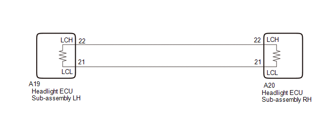
| 2. | CHECK CAN BUS WIRE (HEADLIGHT ECU SUB-ASSEMBLY LH MAIN WIRE) |
(a) Disconnect the cable from the negative (-) auxiliary battery terminal.
(b) Disconnect the A19 headlight ECU sub-assembly LH connector.
(c) Measure the resistance according to the value(s) in the table below.
Standard Resistance:
| Tester Connection | Condition | Specified Condition |
|---|---|---|
| A19-22 (LCH) - A19-21 (LCL) | Cable disconnected from negative (-) auxiliary battery terminal | 108 to 132 Ω |
| A19-22 (LCH) - I182-4 (CG) | Cable disconnected from negative (-) auxiliary battery terminal | 200 Ω or higher |
| A19-21 (LCL) - I182-4 (CG) | Cable disconnected from negative (-) auxiliary battery terminal | 200 Ω or higher |
| A19-22 (LCH) - I182-16 (BAT) | Cable disconnected from negative (-) auxiliary battery terminal | 6 kΩ or higher |
| A19-21 (LCL) - I182-16 (BAT) | Cable disconnected from negative (-) auxiliary battery terminal | 6 kΩ or higher |
| NG | | GO TO STEP 6 |
|
| 3. | CHECK HEADLIGHT ECU SUB-ASSEMBLY RH |
(a) Temporarily replace the headlight ECU sub-assembly RH with a new one.
Click here
|
| 4. | CLEAR DTC |
(a) Connect the Techstream to the DLC3.
(b) Turn the power switch on (IG).
(c) Turn the Techstream on.
(d) Enter the following menus: Body Electrical / AFS / Clear DTCs.
(e) Clear the DTCs.
Body Electrical > AFS > Clear DTCs
|
| 5. | CHECK FOR DTC |
(a) Connect the Techstream to the DLC3.
(b) Turn the power switch on (IG).
(c) Wait 10 seconds or more.
(d) Turn the Techstream on.
(e) Enter the following menus: Body Electrical / AFS / Trouble Codes.
(f) Check for DTCs.
Body Electrical > AFS > Trouble CodesOK:
DTC U0242 is not output.
| OK | | END (HEADLIGHT ECU SUB-ASSEMBLY RH IS DEFECTIVE) |
| NG | | REPLACE HEADLIGHT ECU SUB-ASSEMBLY LH |
| 6. | CHECK CAN BUS WIRE (HEADLIGHT ECU SUB-ASSEMBLY RH MAIN WIRE) |
(a) Disconnect the cable from the negative (-) auxiliary battery terminal.
(b) Disconnect the A20 headlight ECU sub-assembly RH connector.
(c) Measure the resistance according to the value(s) in the table below.
Standard Resistance:
| Tester Connection | Condition | Specified Condition |
|---|---|---|
| A20-22 (LCH) - A20-21 (LCL) | Cable disconnected from negative (-) auxiliary battery terminal | 108 to 132 Ω |
| A20-22 (LCH) - I182-4 (CG) | Cable disconnected from negative (-) auxiliary battery terminal | 200 Ω or higher |
| A20-21 (LCL) - I182-4 (CG) | Cable disconnected from negative (-) auxiliary battery terminal | 200 Ω or higher |
| A20-22 (LCH) - I182-16 (BAT) | Cable disconnected from negative (-) auxiliary battery terminal | 6 kΩ or higher |
| A20-21 (LCL) - I182-16 (BAT) | Cable disconnected from negative (-) auxiliary battery terminal | 6 kΩ or higher |
| NG | | REPAIR OR REPLACE CAN BUS MAIN WIRE OR CONNECTOR |
|
| 7. | CHECK HEADLIGHT ECU SUB-ASSEMBLY RH |
(a) Temporarily replace the headlight ECU sub-assembly RH with a new one.
Click here
|
| 8. | CLEAR DTC |
(a) Connect the Techstream to the DLC3.
(b) Turn the power switch on (IG).
(c) Turn the Techstream on.
(d) Enter the following menus: Body Electrical / AFS / Clear DTCs.
(e) Clear the DTCs.
Body Electrical > AFS > Clear DTCs
|
| 9. | CHECK FOR DTC |
(a) Connect the Techstream to the DLC3.
(b) Turn the power switch on (IG).
(c) Wait 10 seconds or more.
(d) Turn the Techstream on.
(e) Enter the following menus: Body Electrical / AFS / Trouble Codes.
(f) Check for DTCs.
Body Electrical > AFS > Trouble CodesOK:
DTC U0242 is not output.
| OK | | END (HEADLIGHT ECU SUB-ASSEMBLY RH IS DEFECTIVE) |
| NG | | REPLACE HEADLIGHT ECU SUB-ASSEMBLY LH |
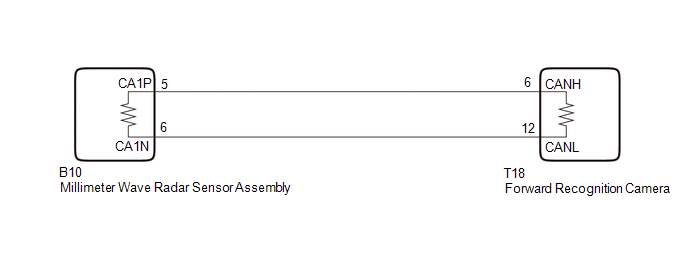
| 10. | CHECK CAN BUS WIRE (FORWARD RECOGNITION CAMERA MAIN WIRE) |
(a) Disconnect the cable from the negative (-) auxiliary battery terminal.
(b) Disconnect the T18 forward recognition camera connector.
(c) Measure the resistance according to the value(s) in the table below.
Standard Resistance:
| Tester Connection | Condition | Specified Condition |
|---|---|---|
| T18-6 (CANH) - T18-12 (CANL) | Cable disconnected from negative (-) auxiliary battery terminal | 108 to 132 Ω |
| T18-6 (CANH) - I182-4 (CG) | Cable disconnected from negative (-) auxiliary battery terminal | 200 Ω or higher |
| T18-12 (CANL) - I182-4 (CG) | Cable disconnected from negative (-) auxiliary battery terminal | 200 Ω or higher |
| T18-6 (CANH) - I182-16 (BAT) | Cable disconnected from negative (-) auxiliary battery terminal | 6 kΩ or higher |
| T18-12 (CANL) - I182-16 (BAT) | Cable disconnected from negative (-) auxiliary battery terminal | 6 kΩ or higher |
| NG | | GO TO STEP 14 |
|
| 11. | CHECK MILLIMETER WAVE RADAR SENSOR ASSEMBLY |
(a) Temporarily replace the millimeter wave radar sensor assembly with a new one.
Click here
|
| 12. | CLEAR DTC |
(a) Connect the Techstream to the DLC3.
(b) Turn the power switch on (IG).
(c) Turn the Techstream on.
(d) Enter the following menus: Body Electrical / Front Recognition Camera (Front Lighting Control) / Clear DTCs.
(e) Clear the DTCs.
Body Electrical > Front Recognition Camera (Front Lighting Control) > Clear DTCs
|
| 13. | CHECK FOR DTC |
(a) Connect the Techstream to the DLC3.
(b) Turn the power switch on (IG).
(c) Wait 5 seconds or more.
(d) Turn the Techstream on.
(e) Enter the following menus: Body Electrical / Front Recognition Camera (Front Lighting Control) / Trouble Codes.
(f) Check for DTCs.
Body Electrical > Front Recognition Camera (Front Lighting Control) > Trouble CodesOK:
DTC U023587 is not output.
| OK | | END (MILLIMETER WAVE RADAR SENSOR ASSEMBLY IS DEFECTIVE) |
| NG | | REPLACE FORWARD RECOGNITION CAMERA |
| 14. | CHECK CAN BUS WIRE (MILLIMETER WAVE RADAR SENSOR ASSEMBLY MAIN WIRE) |
(a) Disconnect the cable from the negative (-) auxiliary battery terminal.
(b) Disconnect the B10 millimeter wave radar sensor assembly connector.
(c) Measure the resistance according to the value(s) in the table below.
Standard Resistance:
| Tester Connection | Condition | Specified Condition |
|---|---|---|
| B10-5 (CA1P) - B10-6 (CA1N) | Cable disconnected from negative (-) auxiliary battery terminal | 108 to 132 Ω |
| B10-5 (CA1P) - I182-4 (CG) | Cable disconnected from negative (-) auxiliary battery terminal | 200 Ω or higher |
| B10-6 (CA1N) - I182-4 (CG) | Cable disconnected from negative (-) auxiliary battery terminal | 200 Ω or higher |
| B10-5 (CA1P) - I182-16 (BAT) | Cable disconnected from negative (-) auxiliary battery terminal | 6 kΩ or higher |
| B10-6 (CA1N) - I182-16 (BAT) | Cable disconnected from negative (-) auxiliary battery terminal | 6 kΩ or higher |
| NG | | REPAIR OR REPLACE CAN BUS MAIN WIRE OR CONNECTOR |
|
| 15. | CHECK MILLIMETER WAVE RADAR SENSOR ASSEMBLY |
(a) Temporarily replace the millimeter wave radar sensor assembly with a new one.
Click here
|
| 16. | CLEAR DTC |
(a) Connect the Techstream to the DLC3.
(b) Turn the power switch on (IG).
(c) Turn the Techstream on.
(d) Enter the following menus: Body Electrical / Front Recognition Camera (Front Lighting Control) / Clear DTCs.
(e) Clear the DTCs.
Body Electrical > Front Recognition Camera (Front Lighting Control) > Clear DTCs
|
| 17. | CHECK FOR DTC |
(a) Connect the Techstream to the DLC3.
(b) Turn the power switch on (IG).
(c) Wait 5 seconds or more.
(d) Turn the Techstream on.
(e) Enter the following menus: Body Electrical / Front Recognition Camera (Front Lighting Control) / Trouble Codes.
(f) Check for DTCs.
Body Electrical > Front Recognition Camera (Front Lighting Control) > Trouble CodesOK:
DTC U023587 is not output.
| OK | | END (MILLIMETER WAVE RADAR SENSOR ASSEMBLY IS DEFECTIVE) |
| NG | | REPLACE FORWARD RECOGNITION CAMERA |
READ NEXT:
 CAN Communication Failure (Message Registry) (U1000)
DESCRIPTION This DTC is output when an internal malfunction of the CAN communication-related ECU is stored. DTC No. Detection Item DTC Detection Condition Trouble Area U1000 CAN Communi
Turn Signal Switch Circuit
DESCRIPTION The combination meter receives the turn signal switch information and controls the turn signal lights. WIRING DIAGRAM CAUTION / NOTICE / HINT NOTICE: When replacing the combination meter
Headlight Dimmer Switch Circuit
DESCRIPTION The main body ECU (multiplex network body ECU) receives light control switch signals, dimmer switch signals, fog light switch signals from the headlight dimmer switch. WIRING DIAGRAM CAUT
SEE MORE:
Main Body ECU Communication Stop Mode
DESCRIPTION Detection Item Symptom Trouble Area Main Body ECU Communication Stop Mode Any of the following conditions are met:
Communication stop for "Main Body" is indicated on the "Communication Bus Check" screen of the Techstream.
Click here
Communication system DTCs (DTCs t
A/C Inverter Start-up Signal System Malfunction (B1473)
DESCRIPTION The inverter activation signal is sent to the compressor with motor assembly from the hybrid vehicle control ECU. Compressor control is stopped and this DTC is stored if there is an open or short in the signal circuit. DTC No. Detection Item DTC Detection Condition Trouble Area
