Lexus NX: Power Back Door cannot be Opened or Closed Using the Power Back Door Switch
DESCRIPTION
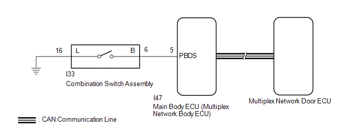
When the power back door cannot be opened or closed using the combination switch assembly, one of the following may be malfunctioning: 1) combination switch assembly circuit, 2) multiplex network door ECU or 3) main body ECU (multiplex network body ECU).
WIRING DIAGRAM
CAUTION / NOTICE / HINT
NOTICE:
-
First perform the communication function inspections in How to Proceed with Troubleshooting to confirm that there are no CAN communication malfunctions before troubleshooting this problem.
Click here
.gif)
-
If the replacement, removal and installation of the multiplex network door ECU or disconnection of the connectors of the multiplex network door ECU has been performed, initialize the power back door system.
Click here
- Recognition code registration is necessary when replacing the main body ECU (multiplex network body ECU).
-
If the main body ECU (multiplex network body ECU) is replaced, refer to Registration.
Click here
PROCEDURE
| 1. | READ VALUE USING TECHSTREAM |
(a) Read the Data List according to the display on the Techstream.
Click here
| Tester Display | Measurement Item | Range | Normal Condition | Diagnostic Note |
|---|---|---|---|---|
| Back Door Open SW | Combination switch assembly signal | ON or OFF | ON: Combination switch assembly pushed OFF: Combination switch assembly not pushed | - |
| Tester Display |
|---|
| Back Door Open SW |
OK:
The combination switch assembly functions as specified in the normal condition column.
| NG | .gif) | GO TO STEP 5 |
|
.gif)
| 2. | REPLACE MULTIPLEX NETWORK DOOR ECU |
(a) Temporarily replace the multiplex network door ECU with a new or normally functioning one.
Click here
|
| 3. | INITIALIZE MULTIPLEX NETWORK DOOR ECU |
(a) Perform the initialization for the multiplex network door ECU.
Click here
|
| 4. | CHECK POWER BACK DOOR SYSTEM |
(a) Check that the power back door operates normally.
Click here
OK:
Power back door operates normally
| OK | | END (MULTIPLEX NETWORK DOOR ECU WAS DEFECTIVE) |
| NG | | REPLACE MAIN BODY ECU (MULTIPLEX NETWORK BODY ECU) |
| 5. | INSPECT COMBINATION SWITCH ASSEMBLY |
(a) Remove the combination switch assembly.
Click here
(b) Inspect the combination switch assembly.
Click here
| NG | | REPLACE COMBINATION SWITCH ASSEMBLY |
|
| 6. | CHECK HARNESS AND CONNECTOR (COMBINATION SWITCH ASSEMBLY - MAIN BODY ECU [MULTIPLEX NETWORK BODY ECU] AND BODY GROUND) |
(a) Disconnect the I33 combination switch assembly connector.
(b) Disconnect the I47 main body ECU (multiplex network body ECU) connector.
(c) Measure the resistance according to the value(s) in the table below.
Standard Resistance:
| Tester Connection | Condition | Specified Condition |
|---|---|---|
| I33-6 (B) - I47-5 (PBDS) | Always | Below 1 Ω |
| I33-16 (L) - Body ground | Always | Below 1 Ω |
| I33-6 (B) or I47-5 (PBDS) - Body ground | Always | 10 kΩ or higher |
| OK | | REPLACE MAIN BODY ECU (MULTIPLEX NETWORK BODY ECU) |
| NG | | REPAIR OR REPLACE HARNESS OR CONNECTOR |
READ NEXT:
 Power Back Door cannot be Opened or Closed Using the Back Door Control Switch
DESCRIPTION When the power back door cannot be closed using the back door control switch, either of the following may be malfunctioning: 1) back door control switch circuit or 2) multiplex network doo
Power Back Door cannot be Opened Using the Back Door Opener Switch
DESCRIPTION The multiplex network door ECU receives an open signal from the back door opener switch assembly via the certification ECU (smart key ECU assembly). WIRING DIAGRAM CAUTION / NOTICE / HINT
Power Back Door Warning System does not Operate
DESCRIPTION When the power back door warning system does not operate, one of the following may be malfunctioning: 1) wireless door lock control system, 2) power back door warning buzzer circuit or 3)
SEE MORE:
Components
COMPONENTS ILLUSTRATION *1 DECK FLOOR BOX LH *2 NO. 3 DECK BOARD SUB-ASSEMBLY *3 REAR DECK FLOOR BOX *4 NEGATIVE AUXILIARY BATTERY TERMINAL N*m (kgf*cm, ft.*lbf): Specified torque - - ILLUSTRATION *1 NO. 1 BLACK OUT TAPE LH *2 NO. 2 BLACK OUT TAPE LH *
Internal Control Module EEPROM Error (P062F)
DESCRIPTION The ECM monitors its internal operation and stores this DTC when it detects an internal malfunction. DTC No. Detection Item DTC Detection Condition Trouble Area MIL Memory P062F Internal Control Module EEPROM Error An ECM internal error (EEPROM) (1 trip detection log
