Lexus NX: Sensor Power Supply "A" Circuit / Open (P06B0-163,P06D6-511,P06E6-164,P0A1B-786,P0A1B-794,P1C2B-192,P1C73-512,P1CA7-193,P3134-661)
DESCRIPTION
The MG ECU, which is built into the inverter with converter assembly, monitors its internal operation and will store DTCs if the system is malfunctioning. If any of the following DTCs are output, replace the inverter with converter assembly.
| DTC No. | Detection Item | DTC Detection Condition | Trouble Area | MIL | Warning Indicate |
|---|---|---|---|---|---|
| P06B0-163 | Sensor Power Supply "A" Circuit / Open | MG ECU internal malfunction: IPM positive power source error (1 trip detection logic) | Inverter with converter assembly | Comes on | Master Warning Light: Comes on |
| P06D6-511 | Sensor Reference Voltage "F" Circuit / Open | MG ECU internal malfunction: Standard voltage for analog signal offset (+2.5 V) error (1 trip detection logic) | Inverter with converter assembly | Comes on | Master Warning Light: Comes on |
| P06E6-164 | Sensor Power Supply "C" Circuit / Open | MG ECU internal malfunction: IPM negative power source error (1 trip detection logic) | Inverter with converter assembly | Comes on | Master Warning Light: Comes on |
| P0A1B-786 | Drive Motor "A" Control Module | MG ECU internal malfunction: Calculation check error (1 trip detection logic) | Inverter with converter assembly | Comes on | Master Warning Light: Comes on |
| P0A1B-794 | Drive Motor "A" Control Module | MG ECU internal malfunction: R/D converter communication error (1 trip detection logic) | Inverter with converter assembly | Comes on | Master Warning Light: Comes on |
| P1C2B-192 | Drive Motor "A" A/D Converter Circuit | MG ECU internal malfunction: A/D converter malfunction (1 trip detection logic) | Inverter with converter assembly | Comes on | Master Warning Light: Comes on |
| P1C73-512 | Sensor Standard Voltage "F" Circuit / Open | MG ECU internal malfunction: Standard voltage for analog signal (+5 V) error (1 trip detection logic) | Inverter with converter assembly | Comes on | Master Warning Light: Comes on |
| P1CA7-193 | Drive Motor Control Module Malfunction | MG ECU internal malfunction: CPU ROM-RAM error (1 trip detection logic) | Inverter with converter assembly | Comes on | Master Warning Light: Comes on |
| P3134-661 | Communication Error from Drive Motor "A" to Generator | MG ECU internal malfunction: Communication error (from motor (MG2) to generator (MG1)) (1 trip detection logic) | Inverter with converter assembly | Comes on | Master Warning Light: Comes on |
| DTC No. | Data List |
|---|---|
| P0A1B-794 | Motor (MG2) Revolution |
| P06B0-163 P06D6-511 P06E6-164 P0A1B-786 P1C2B-192 P1C73-512 P1CA7-193 P3134-661 | - |
MONITOR DESCRIPTION
The MG ECU (in the inverter with converter assembly) performs many diagnostic tests to verify proper operation of internal ECU systems. In one of these tests, the MG ECU checks the result of the motor CPU self-test. If the MG ECU detects a "Fail" from the motor CPU self-test, it will conclude that there is an internal malfunction in the motor CPU and the hybrid vehicle control ECU will illuminate the MIL and store a DTC.
MONITOR STRATEGY
| Related DTCs | P06B0 (INF 163): Motor CPU power malfunction (26 V) P06D6 (INF 511): Motor CPU power malfunction (2.5 V) P06E6 (INF 164): Motor CPU power malfunction (-5 V) P0A1B (INF 786): MG CPU ALU malfunction P0A1B (INF 794): R/D converter communication malfunction P1C2B (INF 192): A/D malfunction (2 MG CPU) P1C73 (INF 512): Motor CPU power malfunction (5 VAref) P1CA7 (INF 193): RAM and ROM destruction P3134 (INF 661): 2 MG CPU communication malfunction (2 MG CPU to 1 MG CPU) |
| Required sensors/components | Inverter with converter assembly (MG ECU) |
| Frequency of operation | Continuous |
| Duration | TMC's intellectual property |
| MIL operation | 1 driving cycle |
| Sequence of operation | None |
TYPICAL ENABLING CONDITIONS
| The monitor will run whenever the following DTCs are not stored | TMC's intellectual property |
| Other conditions belong to TMC's intellectual property | - |
TYPICAL MALFUNCTION THRESHOLDS
| TMC's intellectual property | - |
COMPONENT OPERATING RANGE
| Hybrid vehicle control ECU | DTC P06B0 (INF 163) is not detected DTC P06D6 (INF 511) is not detected DTC P06E6 (INF 164) is not detected DTC P0A1B (INF 786/794) is not detected DTC P1C2B (INF 192) is not detected DTC P1C73 (INF 512) is not detected DTC P1CA7 (INF 193) is not detected DTC P3134 (INF 661) is not detected |
CONFIRMATION DRIVING PATTERN
- Connect the Techstream to the DLC3.
- Turn the power switch on (IG) and turn the Techstream on.
- Clear the DTCs (even if no DTCs are stored, perform the clear DTC procedure).
- Turn the power switch off and wait for 30 seconds or more.
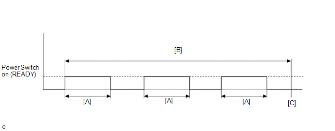
- Turn the power switch on (READY) and after 1 minute or more, turn the power switch off. [A]
- Repeat [A] 3 times. [B]
- Turn the power switch on (IG) and turn the Techstream on.
- Enter the following menus: Powertrain / Hybrid Control / Trouble Codes. [C]
-
Read the current DTCs.
HINT:
- If a current DTC is output, the system is malfunctioning.
- If current DTCs are not output, check for permanent DTCs.
- Check that the permanent DTCs are cleared.
- If the permanent DTCs are not cleared, perform the universal trip, and then check for permanent DTCs again.
CAUTION / NOTICE / HINT
HINT:
-
If DTC P06B0-163, P06D6-511, P06E6-164, P0A1B-786, P0A1B-794, P1C2B-192, P1C73-512 or P3134-661 is output, clear the DTCs, perform the following procedure, and check that the same DTC is not output after the repair.
- Turn the power switch on (IG) and wait for 5 seconds or more.
-
If DTC P1CA7-193 is output, clear the DTCs, perform the following procedure, and check that the same DTC is not output after the repair.
- Turn the power switch on (IG) and wait for 1 minute or more.
PROCEDURE
| 1. | REPLACE INVERTER WITH CONVERTER ASSEMBLY |
Click here .gif)
| NEXT | .gif) | COMPLETED |
READ NEXT:
 Transmission Range Sensor Circuit (P0705-757)
DESCRIPTION The shift lever position sensor sends 7 different switch signals to the hybrid vehicle control ECU. The hybrid vehicle control ECU uses these signals to detect the shift lever position (P,
Motor Electronics Coolant Temperature Sensor Circuit Range / Performance (P0A01-726,P0A04-725)
DTC SUMMARY MALFUNCTION DESCRIPTION These DTCs indicate the temperature sensor value is abnormal. The cause of this malfunction may be one of the following: Area Main Malfunction Description St
Motor Electronics Coolant Temperature Sensor Circuit Low (P0A02-719,P0A03-720)
DESCRIPTION Refer to the description for DTC P0A01-726. Click here DTC No. Detection Item DTC Detection Condition Trouble Area MIL Warning Indicate P0A02-719 Motor Electronics Coo
SEE MORE:
Problem Symptoms Table
PROBLEM SYMPTOMS TABLE HINT: Use the table below to help determine the cause of problem symptoms. If multiple suspected areas are listed, the potential causes of the symptoms are listed in order of probability in the "Suspected Area" column of the table. Check each symptom by checking the suspected
Front Door Opening Trim Weatherstrip
ComponentsCOMPONENTS ILLUSTRATION *1 DOOR SCUFF PLATE ASSEMBLY LH *2 FRONT DOOR OPENING TRIM WEATHERSTRIP LH RemovalREMOVAL CAUTION / NOTICE / HINT HINT:
Use the same procedure for the RH and LH side.
The procedure listed below is for the LH side.
PROCEDURE 1. REMOVE DOOR SCUF
