Lexus NX: "CHK" message(s) are displayed on the SIGNAL CHECK screen.
DESCRIPTION
On the SIGNAL CHECK screen, it is possible to check if the signals sent to the parking assist ECU are normal.
Click here .gif)
HINT:
- On the SIGNAL CHECK screen, "OK" (blue) is displayed for items with a normal inspection result or input state.
- On the SIGNAL CHECK screen, "CHK" (red) is displayed for items with an abnormal inspection result or input state.
- Displayed items may differ depending on vehicle specifications.
| Item | Signal Input Method | Detail | DTC Output when Abnormal Result is Displayed | Signal Receiver |
|---|---|---|---|---|
| CAN | CAN communication | CAN communication signal | DTC is output | Related ECUs |
| CAMERA SW | Vehicle wire harness | No. 2 combination switch assembly (panoramic view monitor main switch) signal input state | DTC is not output | No. 2 Combination Switch Assembly (Panoramic View Monitor Main Switch) |
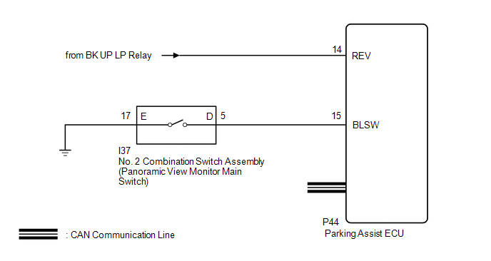
WIRING DIAGRAM
CAUTION / NOTICE / HINT
NOTICE:
-
When "!" mark is displayed on the multi-display assembly after the auxiliary battery cable is disconnected, correct the steering angle neutral point.
Click here
-
Depending on the parts that are replaced or operations that are performed during vehicle inspection or maintenance, calibration of other systems as well as the panoramic view monitor system may be needed.
Click here
PROCEDURE
| 1. | CHECK DISPLAY CHECK MODE |
| (a) Check which items display on the signal check screen. |
|
.png)
| Result | Proceed to |
|---|---|
| "CAMERA SW" displays "CHK" (red) | A |
| "SHIFT" displays "CHK" (red) | B |
| "CAN" displays "CHK" (red) | C |
| B | .gif) | GO TO STEP 4 |
| C | | GO TO CAN COMMUNICATION SYSTEM |
|
.gif)
| 2. | CHECK HARNESS AND CONNECTOR (NO. 2 COMBINATION SWITCH ASSEMBLY [PANORAMIC VIEW MONITOR MAIN SWITCH] - PARKING ASSIST ECU AND BODY GROUND) |
(a) Disconnect the I37 No. 2 combination switch assembly (panoramic view monitor main switch) connector.
(b) Disconnect the P44 parking assist ECU connector.
(c) Measure the resistance according to the value(s) in the table below.
Standard Resistance:
| Tester Connection | Condition | Specified Condition |
|---|---|---|
| P44-15 (BLSW) - I37-5 (D) | Always | Below 1 Ω |
| I37-17 (E) - Body ground | Always | Below 1 Ω |
| P44-15 (BLSW) - Body ground | Always | 10 kΩ or higher |
| NG | | REPAIR OR REPLACE HARNESS OR CONNECTOR |
|
| 3. | INSPECT NO. 2 COMBINATION SWITCH ASSEMBLY (PANORAMIC VIEW MONITOR MAIN SWITCH) |
(a) Remove the No. 2 combination switch assembly (panoramic view monitor main switch).
Click here
(b) Inspect the No. 2 combination switch assembly (panoramic view monitor main switch).
Click here
| OK | | REPLACE PARKING ASSIST ECU |
| NG | | REPLACE NO. 2 COMBINATION SWITCH ASSEMBLY |
| 4. | CHECK BACK-UP LIGHT |
(a) Check that the back-up light comes on.
OK:
The back-up light comes on.
| NG | | GO TO LIGHTING SYSTEM (EXT) |
|
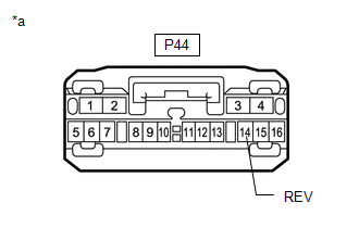
| 5. | CHECK HARNESS AND CONNECTOR (REVERSE SIGNAL) |
| (a) Disconnect the parking assist ECU connector. |
|
(b) Measure the voltage according to the value(s) in the table below.
Standard Voltage:
| Tester Connection | Condition | Specified Condition |
|---|---|---|
| P44-14 (REV) - Body ground | Power switch on (IG) Shift position in R | 11 to 14 V |
| P44-14 (REV) - Body ground | Power switch on (IG) Shift position not in R | Below 1 V |
| OK | | REPLACE PARKING ASSIST ECU |
| NG | | REPAIR OR REPLACE HARNESS OR CONNECTOR |
READ NEXT:
 ECU Power Source Circuit
DESCRIPTION This circuit is the power source circuit to operate the parking assist ECU. The parking assist ECU controls the panoramic view monitor system. WIRING DIAGRAM CAUTION / NOTICE / HINT NOTIC
Image from Camera for Panoramic View Monitor is Abnormal
DESCRIPTION The display signal from the rear television camera assembly is transmitted to the multi-display assembly via the parking assist ECU. WIRING DIAGRAM w/o Seat Memory w/ Seat Memory CAUTION
SEE MORE:
Rear Power Window RH does not Operate with Rear Power Window Switch RH
DESCRIPTION When the power switch is on (IG), the rear power window regulator motor assembly RH is operated by the rear power window regulator switch assembly (for rear RH door). The rear power window regulator motor assembly RH has motor, regulator and ECU functions. WIRING DIAGRAM CAUTION / NOTIC
Relay
On-vehicle InspectionON-VEHICLE INSPECTION PROCEDURE 1. INSPECT IGNITION CONTROL RELAY (IGCT) (a) Measure the resistance according to the value(s) in the table below. Standard Resistance: Tester Connection Condition Specified Condition 3 - 5 Auxiliary battery voltage is not applied
