Lexus NX: ECU Power Source Circuit
DESCRIPTION
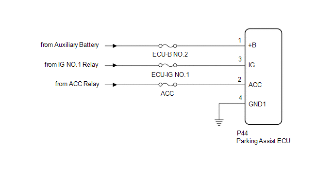
This circuit is the power source circuit to operate the parking assist ECU. The parking assist ECU controls the panoramic view monitor system.
WIRING DIAGRAM
CAUTION / NOTICE / HINT
NOTICE:
Inspect the fuse for circuits related to this system before performing the following procedure.
HINT:
- If the television camera controller does not operate due to a power source problem, other system DTCs may be stored due to a CAN communication interruption.
PROCEDURE
| 1. | CHECK HARNESS AND CONNECTOR (PARKING ASSIST ECU - BATTERY AND BODY GROUND) |
| (a) Disconnect the parking assist ECU connector. |
|
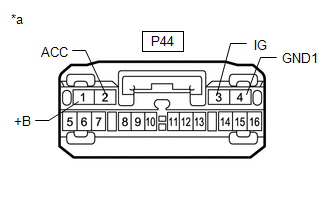
(b) Measure the resistance according to the value(s) in the table below.
Standard Resistance:
| Tester Connection | Condition | Specified Condition |
|---|---|---|
| P44-4 (GND1) - Body ground | Always | Below 1 Ω |
(c) Measure the voltage according to the value(s) in the table below.
Standard Voltage:
| Tester Connection | Switch Condition | Specified Condition |
|---|---|---|
| P44-1 (+B) - P44-4 (GND1) | Power switch off | 11 to 14 V |
| P44-2 (ACC) - P44-4 (GND1) | Power switch on (ACC) | 11 to 14 V |
| Power switch off | Below 1 V | |
| P44-3 (IG) - P44-4 (GND1) | Power switch on (IG) | 11 to 14 V |
| Power switch off | Below 1 V |
| OK | .gif) | PROCEED TO NEXT SUSPECTED AREA SHOWN IN PROBLEM SYMPTOMS TABLE |
.gif)
| NG | | REPAIR OR REPLACE HARNESS OR CONNECTOR |
READ NEXT:
 Image from Camera for Panoramic View Monitor is Abnormal
DESCRIPTION The display signal from the rear television camera assembly is transmitted to the multi-display assembly via the parking assist ECU. WIRING DIAGRAM w/o Seat Memory w/ Seat Memory CAUTION
Components
COMPONENTS ILLUSTRATION *1 DECK TRIM SIDE PANEL ASSEMBLY RH *2 LUGGAGE HOLD BELT STRIKER ASSEMBLY *3 NO. 1 LUGGAGE COMPARTMENT TRIM HOOK *4 PARKING ASSIST ECU *5 REAR DOOR OP
SEE MORE:
Installation
INSTALLATION PROCEDURE 1. INSTALL SHIFT LEVER POSITION SENSOR (a) Install the shift lever position sensor to the manual valve shaft. (b) Temporarily install the 2 bolts. (c) Install the lock plate and tighten the lock nut. Torque: 6.9 N·m {70 kgf·cm, 61 in·lbf} (d) Temporarily install the contro
Inspection
INSPECTION PROCEDURE 1. INSPECT BACK DOOR LOCK ASSEMBLY (w/o Power Back Door) (a) Check the operation of the door lock motor. (1) Move the back door lock assembly to the lock position. (2) Apply auxiliary battery voltage to the door lock motor assembly and check the operation of the door lock mot
