Lexus NX: Actuator Power Source Circuit
DESCRIPTION
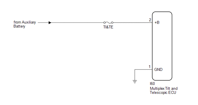
This is the power source for the power tilt and power telescopic steering column system.
WIRING DIAGRAM
CAUTION / NOTICE / HINT
NOTICE:
Inspect the fuses for circuits related to this system before performing the following procedure.
PROCEDURE
| 1. | CHECK HARNESS AND CONNECTOR (MULTIPLEX TILT AND TELESCOPIC ECU - AUXILIARY BATTERY) |
| (a) Disconnect the I60 multiplex tilt and telescopic ECU connector. |
|
.png)
(b) Measure the voltage according to the value(s) in the table below.
Standard Voltage:
| Tester Connection | Condition | Specified Condition |
|---|---|---|
| I60-2 (+B) - Body ground | Always | 11 to 14 V |
| NG | .gif) | REPAIR OR REPLACE HARNESS OR CONNECTOR |
|
.gif)
| 2. | CHECK HARNESS AND CONNECTOR (MULTIPLEX TILT AND TELESCOPIC ECU - BODY GROUND) |
| (a) Disconnect the I60 multiplex tilt and telescopic ECU connector. |
|
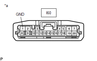
(b) Measure the resistance according to the value(s) in the table below.
Standard Resistance:
| Tester Connection | Condition | Specified Condition |
|---|---|---|
| I60-1 (GND) - Body ground | Always | Below 1 Ω |
| OK | | REPLACE MULTIPLEX TILT AND TELESCOPIC ECU |
.gif)
| NG | | REPAIR OR REPLACE HARNESS OR CONNECTOR |
READ NEXT:
 Tilt and Telescopic Manual Switch Circuit
DESCRIPTION Different voltage values are sent to the multiplex tilt and telescopic ECU by operating the tilt and telescopic switch. The multiplex tilt and telescopic ECU then judges which motor and in
IG Power Source Circuit
DESCRIPTION When the power switch is turned on (IG), the IG power source circuit supplies positive (+) voltage to the multiplex tilt and telescopic ECU. The multiplex tilt and telescopic ECU also rece
SEE MORE:
Removal
REMOVAL PROCEDURE 1. REMOVE MULTI-DISPLAY ASSEMBLY Click here 2. REMOVE DOOR SCUFF PLATE ASSEMBLY LH Click here 3. REMOVE COWL SIDE TRIM BOARD LH Click here 4. REMOVE REAR CONSOLE ARMREST ASSEMBLY Click here 5. REMOVE UPPER REAR CONSOLE PANEL Click here 6. REMOVE UPPER NO. 1 CONSOLE P
Front Recognition Camera Heater Malfunction (C1AAE00)
DESCRIPTION The forward recognition camera controls the current to the forward recognition hood with heater sub-assembly. C1AAE00 is stored when the forward recognition camera detects a forward recognition hood with heater sub-assembly operation circuit malfunction. DTC No. Detection Item DTC
