Lexus NX: Asc Speaker
Components
COMPONENTS
ILLUSTRATION
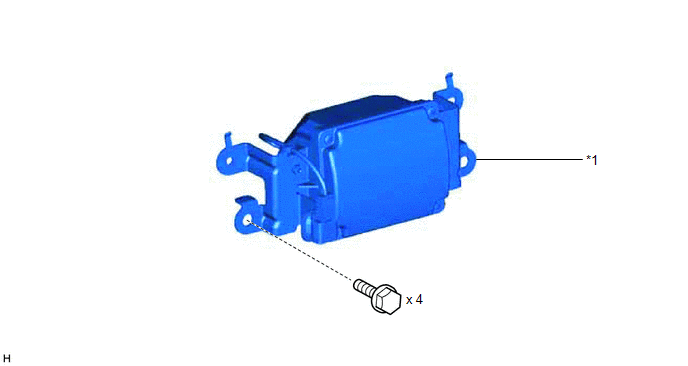
| *1 | NO. 1 SPEAKER ASSEMBLY WITH BOX | - | - |
Removal
REMOVAL
PROCEDURE
1. REMOVE CONSOLE BOX ASSEMBLY
Click here .gif)
2. REMOVE NO. 1 SPEAKER ASSEMBLY WITH BOX
| (a) Remove the 4 bolts and disconnect the connector. |
|
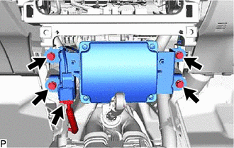
(b) Detach the 2 claws used to temporarily fix the part in place and remove the No. 1 speaker assembly with box.
Inspection
INSPECTION
PROCEDURE
1. INSPECT NO. 1 SPEAKER ASSEMBLY W/ BOX
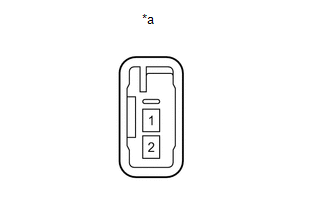
| (a) Measure the resistance according to the value(s) in the table below. Standard Resistance:
If the result is not as specified, replace the No. 1 speaker assembly w/ box. |
|
Installation
INSTALLATION
PROCEDURE
1. INSTALL NO. 1 SPEAKER ASSEMBLY WITH BOX
| (a) Temporarily install the No. 1 speaker assembly with box by attaching the 2 claws of the No. 1 speaker assembly with box to the instrument panel. |
|
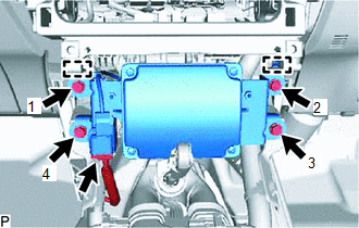
(b) Install the No. 1 speaker assembly with box with the 4 bolts in the order shown in the illustration.
(c) Connect the connector.
2. INSTALL CONSOLE BOX ASSEMBLY
Click here .gif)
READ NEXT:
 Components
COMPONENTS ILLUSTRATION *1 CONSOLE ARMREST ASSEMBLY *2 INSTRUMENT SIDE PANEL LH *3 LOWER NO. 1 INSTRUMENT PANEL FINISH PANEL *4 NO. 1 INSTRUMENT PANEL SAFETY PAD SUB-ASSEMBLY *
Removal
REMOVAL PROCEDURE 1. REMOVE CONSOLE ARMREST ASSEMBLY Click here 2. REMOVE UPPER REAR CONSOLE PANEL Click here 3. REMOVE UPPER NO. 2 CONSOLE PANEL GARNISH Click here 4. REMOVE INSTRUMENT SI
SEE MORE:
Disassembly
DISASSEMBLY CAUTION / NOTICE / HINT HINT:
Use the same procedure for the RH and LH sides.
The procedure listed below is for the LH side.
PROCEDURE 1. REMOVE FRONT TURN SIGNAL LIGHT BULB (a) Turn the bulb socket counterclockwise until the matchmark is aligned with the unlock position mark to
DC / DC Converter Status Circuit (P0A08-264)
DESCRIPTION The DC/DC converter converts the DC 244.8 V of the HV battery into DC 12 V in order to supply power to areas such as the vehicle's lighting, audio, and ECU systems. In addition, it charges the auxiliary battery. A transistor bridge circuit initially converts DC 244.8 V into alternating c
