Lexus NX: Blind Spot Monitor Sensor
Removal
REMOVAL
CAUTION / NOTICE / HINT
NOTICE:
- Avoid any impact to the blind spot monitor sensor.
- Do not drop the blind spot monitor sensor. If it is dropped, replace it with a new one.
PROCEDURE
1. REMOVE REAR BUMPER COVER
Click here .gif)
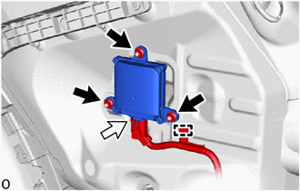
2. REMOVE BLIND SPOT MONITOR SENSOR LH
(a) Remove the clamp.
.png) | Nut |
.png) | Connector |
(b) Disconnect the connector.
| (c) Remove the 3 nuts. NOTICE: If the removed nut is the same shape as that shown in the illustration, replace it the supplied replacement part. |
|

(d) Remove the blind spot monitor sensor LH.
3. REMOVE BLIND SPOT MONITOR SENSOR RH
HINT:
Use the same procedure described for the LH side.
Installation
INSTALLATION
CAUTION / NOTICE / HINT
NOTICE:
- Avoid any impact to the blind spot monitor sensor.
- Do not drop the blind spot monitor sensor. If it is dropped, replace it with a new one.
PROCEDURE
1. INSTALL BLIND SPOT MONITOR SENSOR LH
(a) Connect the connector.
(b) Attach the clamp.
(c) Install the blind spot monitor sensor LH with the 3 nuts.
Torque:
10 N·m {102 kgf·cm, 7 ft·lbf}
NOTICE:
If the removed nut is the same shape as that shown in the illustration, replace it with a new nut of supplied replacement part.
.png)
2. INSTALL BLIND SPOT MONITOR SENSOR RH
HINT:
Use the same procedure described for the LH side.
3. PERFORM BLIND SPOT MONITOR INSTALLATION CONDITION INSPECTION
Click here .gif)
4. INSTALL REAR BUMPER COVER
Click here
5. PERFORM BLIND SPOT MONITOR BEAM AXIS INSPECTION
Click here
6. PERFORM BLIND SPOT MONITOR BEAM AXIS CONFIRMATION
Click here
7. PERFORM DIAGNOSTIC SYSTEM CHECK
Click here
READ NEXT:
 Precaution
PRECAUTION PRECAUTIONS FOR BLIND SPOT MONITOR SYSTEM (a) The blind spot monitor function may not detect vehicles correctly in the following conditions: (1) When the sensor is misaligned due to a stron
Parts Location
PARTS LOCATION ILLUSTRATION *A w/ Panoramic View Monitor System *B w/ Parking Assist Monitor System *1 BLIND SPOT MONITOR SENSOR LH (MASTER) *2 BLIND SPOT MONITOR SENSOR RH (SLAVE)
SEE MORE:
Installation
INSTALLATION PROCEDURE 1. INSTALL TRANSMISSION CONTROL CABLE ASSEMBLY NOTICE: Before installing the transmission control cable assembly, check that the shift lever position sensor and the shift lever are in neutral. (a) Install the transmission control cable assembly to the body with the 2 bolts.
Dtc Combination Table
DTC COMBINATION TABLE HOW TO INTERPRET COMMUNICATION DTCS (DTCS THAT START WITH U) (a) If a CAN communication error cannot be reproduced, determine the suspected malfunctioning part using the DTCs stored in ECUs that are connected to the CAN buses by following the procedure below. HINT: Communicatio
