Lexus NX: Calibration
CALIBRATION
SELECT COMPASS DISPLAY MODE (w/ Compass)
(a) The compass switch allows selection of the compass display.
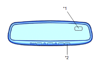
| *1 | Compass Display |
| *2 | Compass Switch |
PERFORM CALIBRATION (w/ Compass)
(a) The compass indicates the direction that the vehicle is heading by detecting the direction and strength of the earth's magnetic field (magnetic north).
(b) Because each vehicle has its own magnetic field, calibration should be performed. The calibration function is used to compensate for the residual magnetism of the vehicle.
WHEN COMPASS IS MAGNETIZED (w/ Compass)
(a) The compass or vehicle may become magnetized while the vehicle is being shipped. As a result, it is necessary to perform calibration for the compass before the vehicle is delivered to the customer. If calibration cannot be performed successfully (calibration cannot be completed despite driving in calibration mode several times), it may be caused by excessive magnetization of the vehicle. Demagnetize the vehicle using a demagnetizer and perform calibration again.
SET COMPASS (w/ Compass)
CALIBRATION MODE (w/ Compass)
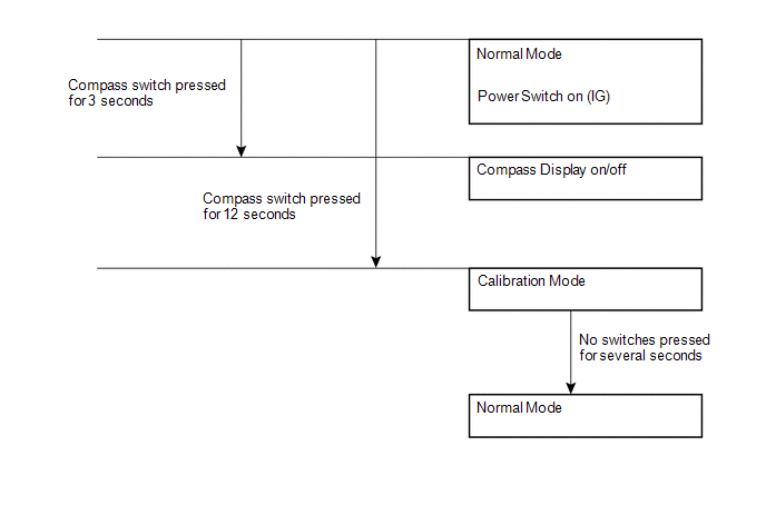
(a) When the compass is in normal mode, pressing the compass switch for 12 seconds will activate calibration mode.
(b) Drive the vehicle in a circle at a speed of 8 km/h (5 mph) or less.
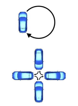
(c) After driving in a circle 1 to 3 times, the direction (N, NE, E, SE, S, SW, W or NW) will be displayed on the compass display. This indicates that calibration has finished.
HINT:
After calibration is performed, it is not necessary to repeat the calibration procedure unless the magnetic field of the vehicle changes drastically. If the magnetic field changes drastically, the compass display will indicate "C".
READ NEXT:
 Problem Symptoms Table
PROBLEM SYMPTOMS TABLE HINT: Use the table below to help determine the cause of problem symptoms. If multiple suspected areas are listed, the potential causes of the symptoms are listed in order of pr
Removal
REMOVAL PROCEDURE 1. REMOVE NO. 2 FORWARD RECOGNITION COVER Click here 2. REMOVE NO. 1 FORWARD RECOGNITION COVER Click here 3. REMOVE INNER REAR VIEW MIRROR ASSEMBLY (a) Disconnect the connec
Inspection
INSPECTION PROCEDURE 1. INSPECT INNER REAR VIEW MIRROR ASSEMBLY (a) Inspect the operation of the electrochromic inner rear view mirror assembly. (1) Connect a positive (+) lead from the battery to ter
SEE MORE:
Disassembly
DISASSEMBLY CAUTION / NOTICE / HINT NOTICE: Do not allow any dirt (fingerprints, grease, etc.) to adhere to the meter glass. If the glass is dirty, wipe it clean with a soft cloth. PROCEDURE 1. REMOVE COMBINATION METER GLASS (a) Using a screwdriver, detach the 8 claws and remove the combination m
Inspection
INSPECTION CAUTION / NOTICE / HINT NOTICE:
When using a vise, place aluminum plates between the part and vise.
When using a vise, do not overtighten it.
PROCEDURE 1. INSPECT REAR DRIVE SHAFT ASSEMBLY (a) Check that there is no excessive play in the radial direction of the inboard joint an
