Lexus NX: Components
COMPONENTS
ILLUSTRATION
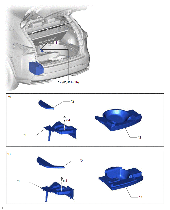
| *A | for Compact Spare Tire | *B | for Full Size Spare Tire |
| *1 | DECK FLOOR BOX LH | *2 | NO. 3 DECK BOARD SUB-ASSEMBLY |
| *3 | REAR DECK FLOOR BOX | *4 | NEGATIVE AUXILIARY BATTERY TERMINAL |
.png) | N*m (kgf*cm, ft.*lbf): Specified torque | - | - |
ILLUSTRATION
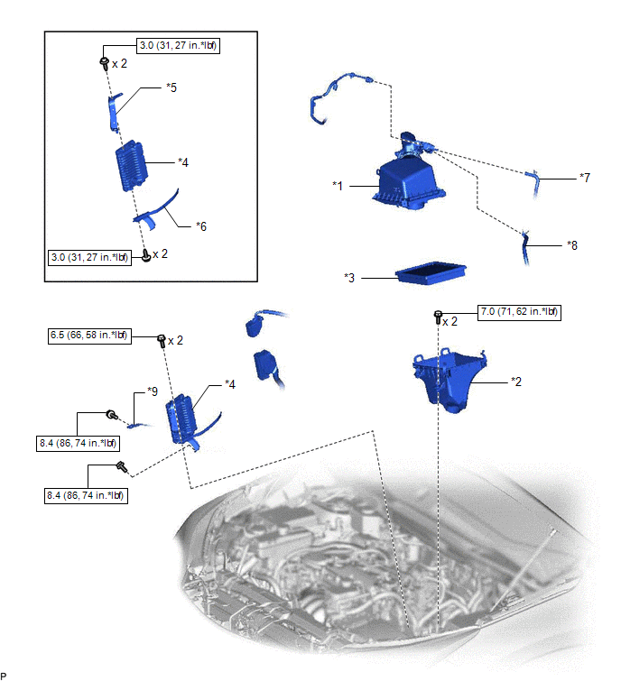
| *1 | AIR CLEANER CAP AND HOSE | *2 | AIR CLEANER CASE SUB-ASSEMBLY |
| *3 | AIR CLEANER FILTER ELEMENT SUB-ASSEMBLY | *4 | ECM |
| *5 | NO. 1 ECM BRACKET | *6 | NO. 2 ECM BRACKET |
| *7 | FUEL VAPOR FEED HOSE | *8 | NO. 2 FUEL VAPOR FEED HOSE |
| *9 | WIRE HARNESS | - | - |
| | N*m (kgf*cm, ft.*lbf): Specified torque | - | - |
READ NEXT:
 Removal
REMOVAL PROCEDURE 1. PRECAUTION NOTICE: After turning the power switch off, waiting time may be required before disconnecting the cable from the negative (-) auxiliary battery terminal. Therefore, mak
Installation
INSTALLATION PROCEDURE 1. INSTALL NO. 2 ECM BRACKET (a) Install the No. 2 ECM bracket to the ECM with the 2 screws. Torque: 3.0 N·m {31 kgf·cm, 27 in·lbf} 2. INSTALL NO. 1 ECM BRACKET (a) Install
SEE MORE:
DCM Data Signal Circuit between Navigation ECU and DCM
DESCRIPTION This circuit is used to send and receive signals between the DCM (telematics transceiver) and radio receiver assembly. WIRING DIAGRAM PROCEDURE 1. CHECK HARNESS AND CONNECTOR (DCM [TELEMATICS TRANSCEIVER] - RADIO RECEIVER ASSEMBLY) (a) Disconnect the I153 radio receiver assembl
Inspection
INSPECTION PROCEDURE 1. INSPECT SHIFT LEVER POSITION SENSOR (a) Measure the resistance according to the value(s) in the table below. Standard Resistance: Tester Connection Condition Specified Condition 7 (+B) - 3 (PR) Shift lever in P Below 1 Ω 7 (+B) - 4 (PNB) Below 1 Ω
© 2016-2024 Copyright www.lexunx.com
