Lexus NX: DCM Data Signal Circuit between Navigation ECU and DCM
DESCRIPTION
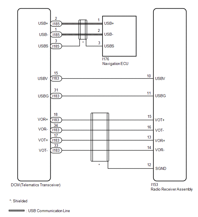
This circuit is used to send and receive signals between the DCM (telematics transceiver) and radio receiver assembly.
WIRING DIAGRAM
PROCEDURE
| 1. | CHECK HARNESS AND CONNECTOR (DCM [TELEMATICS TRANSCEIVER] - RADIO RECEIVER ASSEMBLY) |
(a) Disconnect the I153 radio receiver assembly connector.
(b) Disconnect the I183 DCM (telematics transceiver) connector.
(c) Measure the resistance according to the value(s) in the table below.
Standard Resistance:
| Tester Connection | Condition | Specified Condition |
|---|---|---|
| I153-10 (USBV) - I183-15 (USBV) | Always | Below 1 Ω |
| I153-11 (USBG) - I183-31 (USBG) | Always | Below 1 Ω |
| I153-15 (VOT+) - I183-18 (VOR+) | Always | Below 1 Ω |
| I153-16 (VOT-) - I183-34 (VOR-) | Always | Below 1 Ω |
| I153-13 (VOR+) - I183-17 (VOT+) | Always | Below 1 Ω |
| I153-14 (VOR-) - I183-33 (VOT-) | Always | Below 1 Ω |
| I153-10 (USBV) - Body ground | Always | 10 kΩ or higher |
| I153-11 (USBG) - Body ground | Always | 10 kΩ or higher |
| I153-15 (VOT+) - Body ground | Always | 10 kΩ or higher |
| I153-16 (VOT-) - Body ground | Always | 10 kΩ or higher |
| I153-13 (VOR+) - Body ground | Always | 10 kΩ or higher |
| I153-14 (VOR-) - Body ground | Always | 10 kΩ or higher |
| I153-12 (SGND) - Body ground | Always | 10 kΩ or higher |
| NG | .gif) | REPAIR OR REPLACE HARNESS OR CONNECTOR |
|
.gif)
| 2. | CHECK HARNESS AND CONNECTOR (DCM [TELEMATICS TRANSCEIVER] - NAVIGATION ECU) |
| (a) Disconnect the I176 navigation ECU connector. |
|
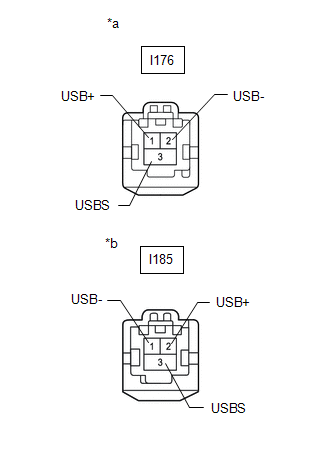
(b) Disconnect the I185 DCM (telematics transceiver) connector.
(c) Measure the resistance according to the value(s) in the table below.
Standard Resistance:
| Tester Connection | Condition | Specified Condition |
|---|---|---|
| I176-1 (USB+) - I185-2 (USB+) | Always | Below 1 Ω |
| I176-2 (USB-) - I185-1 (USB-) | Always | Below 1 Ω |
| I176-3 (USBS) - I185-3 (USBS) | Always | Below 1 Ω |
| I176-1 (USB+) - Body ground | Always | 10 kΩ or higher |
| I176-2 (USB-) - Body ground | Always | 10 kΩ or higher |
| I176-3 (USBS) - Body ground | Always | 10 kΩ or higher |
| OK | | PROCEED TO NEXT SUSPECTED AREA SHOWN IN PROBLEM SYMPTOMS TABLE |
| NG | | REPAIR OR REPLACE HARNESS OR CONNECTOR |
READ NEXT:
 Manual(sos)switch
InspectionINSPECTION PROCEDURE 1. REMOVE MAP LIGHT ASSEMBLY Click here 2. INSPECT MAP LIGHT ASSEMBLY (a) Check the resistance. (1) Measure the resistance according to the value(s) in the table belo
Components
COMPONENTS ILLUSTRATION *1 DECK FLOOR BOX LH *2 NO. 3 DECK BOARD SUB-ASSEMBLY *3 REAR DECK FLOOR BOX *4 NEGATIVE AUXILIARY BATTERY TERMINAL N*m (kgf*cm, ft.*lbf): Specified
SEE MORE:
Lost Communication with Brake System Control Module (U0129,U0140,U0293)
DESCRIPTION These DTCs are stored when the CAN communication system is malfunctioning. DTC No. Detection Item DTC Detection Condition Trouble Area U0129 Lost Communication with Brake System Control Module The vehicle approaching speaker controller does not receive data from the skid
Fail-safe Chart
FAIL-SAFE CHART FAIL-SAFE CHART Adaptive Variable Suspension System DTC Chart Malfunction Item Fail-safe Operation Fail-safe Deactivation Conditions C1715 C1716 C1717 Acceleration sensor circuit Control stops. Normal condition restored and after next time power switch turned on (I
