Lexus NX: Components
COMPONENTS
ILLUSTRATION
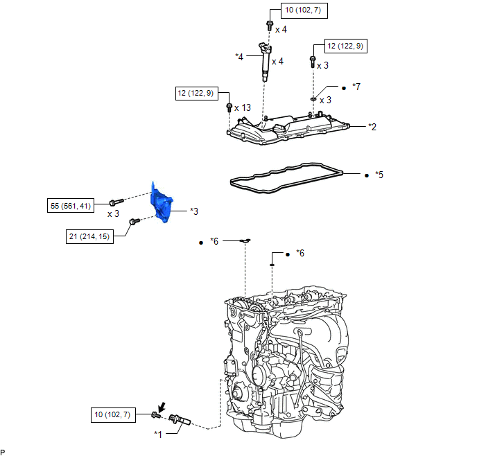
| *1 | CRANKSHAFT POSITION SENSOR | *2 | CYLINDER HEAD COVER SUB-ASSEMBLY |
| *3 | ENGINE MOUNTING BRACKET RH | *4 | IGNITION COIL ASSEMBLY |
| *5 | CYLINDER HEAD COVER GASKET | *6 | GASKET |
| *7 | SEAL WASHER | - | |
.png) | N*m (kgf*cm, ft.*lbf): Specified torque | ● | Non-reusable part |
.png) | Toyota Genuine Adhesive 1324, Three Bond 1324 or equivalent | ★ | Precoated part |
ILLUSTRATION
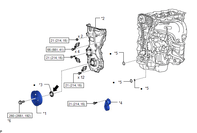
| *1 | CRANKSHAFT PULLEY ASSEMBLY | *2 | TIMING CHAIN COVER ASSEMBLY |
| *3 | TIMING CHAIN COVER OIL SEAL | *4 | V-RIBBED BELT TENSIONER ASSEMBLY |
| *5 | GASKET | *6 | CRANKSHAFT PULLEY SET BOLT |
| | N*m (kgf*cm, ft.*lbf): Specified torque | ● | Non-reusable part |
| | MP grease | .png) | Do not apply lubricants to the threads |
READ NEXT:
 Removal
REMOVAL CAUTION / NOTICE / HINT NOTICE: Do not remove the oil pump and oil pump relief valve from the timing chain cover assembly. PROCEDURE 1. REMOVE ENGINE AND TRANSAXLE Click here 2. REMOVE ENG
Installation
INSTALLATION PROCEDURE 1. INSTALL TIMING CHAIN COVER ASSEMBLY (a) Apply a light coat of engine oil to the 3 new gaskets. (b) Install the 3 gaskets to the stiffening crankcase assembly. (c) Align th
SEE MORE:
Parts Location
PARTS LOCATION ILLUSTRATION *1 FRONT WIPER DEICER RELAY *2 AIR CONDITIONING AMPLIFIER ASSEMBLY *3 MULTI-DISPLAY ASSEMBLY *4 RADIO RECEIVER ASSEMBLY *5 WINDSHIELD GLASS - WINDSHIELD DEICER WIRE *6 NO. 2 ENGINE ROOM RELAY BLOCK *7 DEICER FUSE *8 ECU-B NO.2 FUSE
Relay
On-vehicle InspectionON-VEHICLE INSPECTION PROCEDURE 1. INSPECT LIGHT CUT RELAY (a) Remove the upper instrument panel sub-assembly. Click here (b) Remove the light cut relay. (c) Check the resistance. (1) Measure the resistance according to the value(s) in the table below. Sta
© 2016-2024 Copyright www.lexunx.com
