Lexus NX: Components
COMPONENTS
ILLUSTRATION
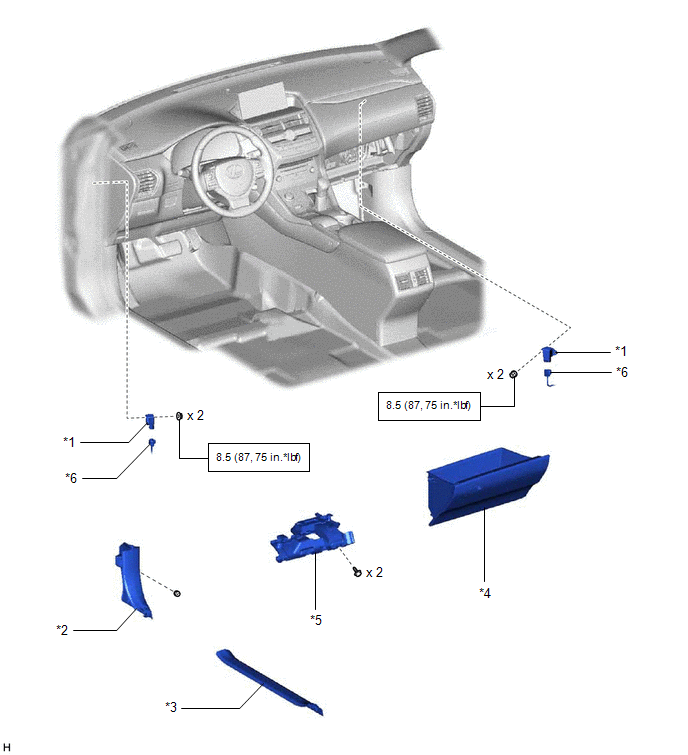
| *1 | ACCELERATION SENSOR | *2 | COWL SIDE TRIM BOARD LH |
| *3 | DOOR SCUFF PLATE ASSEMBLY LH | *4 | GLOVE COMPARTMENT DOOR ASSEMBLY |
| *5 | NO. 1 INSTRUMENT PANEL UNDER COVER SUB-ASSEMBLY | *6 | CONNECTOR |
.png) | N*m (kgf*cm, ft.*lbf): Specified torque | - | - |
READ NEXT:
 Removal
REMOVAL PROCEDURE 1. REMOVE DOOR SCUFF PLATE ASSEMBLY LH Click here 2. REMOVE COWL SIDE TRIM BOARD LH Click here 3. REMOVE NO. 1 INSTRUMENT PANEL UNDER COVER SUB-ASSEMBLY Click here 4. REMOVE GL
Inspection
INSPECTION PROCEDURE 1. INSPECT ACCELERATION SENSOR (a) Connect 3 1.5 V dry cell batteries in series. (b) Connect a positive (+) lead from the batteries to terminal 3 (SGB) and a negative (-) lead to
Installation
INSTALLATION PROCEDURE 1. INSTALL ACCELERATION SENSOR (a) for RH side: (1) Install the acceleration sensor with the 2 nuts. Torque: 8.5 N·m {87 kgf·cm, 75 in·lbf} NOTICE:
Avoid any impact to th
SEE MORE:
Removal
REMOVAL CAUTION / NOTICE / HINT CAUTION: Wear protective gloves. Sharp areas on the parts may injure your hands. PROCEDURE 1. REMOVE REAR SEATBACK ASSEMBLY LH (a) for Manual Seat: Click here (b) for Power Seat: Click here 2. REMOVE REAR SEATBACK ASSEMBLY RH (a) for Manual Seat: Click here (b)
Headlight Cleaner Control Relay(for Triple Beam Headlight)
On-vehicle InspectionON-VEHICLE INSPECTION PROCEDURE 1. INSPECT HEADLIGHT CLEANER CONTROL RELAY (a) Remove the headlight cleaner control relay. (b) Measure the resistance according to the value(s) in the table below. Standard Resistance: Tester Connection Condition Specified Condition
© 2016-2024 Copyright www.lexunx.com
