Lexus NX: Components
COMPONENTS
ILLUSTRATION
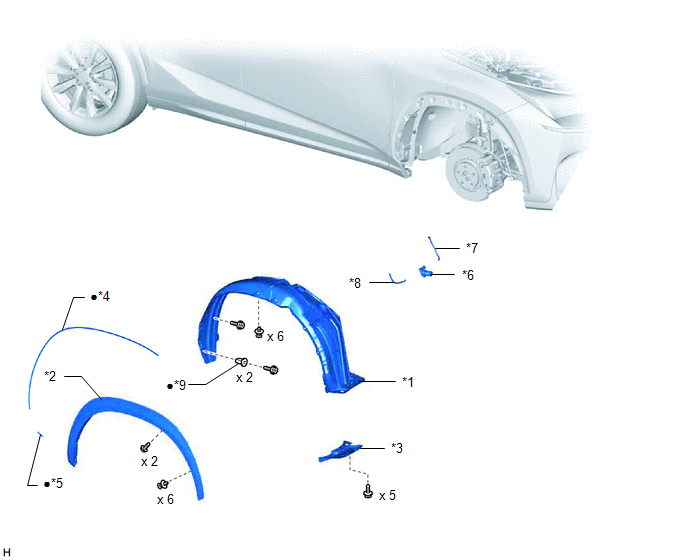
| *1 | FRONT FENDER FRONT SPLASH SHIELD RH | *2 | FRONT FENDER LINER RH |
| *3 | FRONT FENDER MOULDING SUB-ASSEMBLY RH | *4 | NO. 1 MOULDING TAPE |
| *5 | NO. 2 MOULDING TAPE | *6 | WINDSHIELD WASHER MOTOR AND PUMP ASSEMBLY |
| *7 | WASHER HOSE | *8 | REAR WASHER HOSE |
| *9 | GROMMET | - | - |
| ● | Non-reusable part | - | - |
ILLUSTRATION
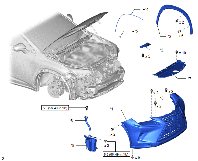
| *1 | FRONT BUMPER COVER | *2 | FRONT FENDER FRONT SPLASH SHIELD LH |
| *3 | FRONT FENDER MOULDING SUB-ASSEMBLY LH | *4 | NO. 1 MOULDING TAPE |
| *5 | NO. 2 MOULDING TAPE | *6 | RADIATOR GRILLE PROTECTOR |
| *7 | RADIATOR SUPPORT OPENING COVER | *8 | WASHER INLET SUB-ASSEMBLY |
| *9 | WINDSHIELD WASHER JAR ASSEMBLY | - | - |
.png) | N*m (kgf*cm, ft.*lbf) : Specified torque | ● | Non-reusable part |
ILLUSTRATION
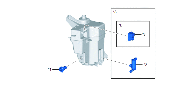
| *A | w/ Headlight Cleaner System | *B | for Single Beam Headlight |
| *1 | LEVEL WARNING SWITCH ASSEMBLY | *2 | HEADLIGHT CLEANER MOTOR AND PUMP ASSEMBLY |
| *3 | HEADLIGHT CLEANER CONTROL RELAY | - | - |
READ NEXT:
 Removal
REMOVAL PROCEDURE 1. REMOVE FRONT WHEEL RH Click here 2. REMOVE FRONT FENDER MOULDING SUB-ASSEMBLY RH HINT: Use the same procedure described for the LH side. Click here 3. REMOVE NO. 1 MOULDING TA
Inspection
INSPECTION PROCEDURE 1. INSPECT WINDSHIELD WASHER MOTOR AND PUMP ASSEMBLY (for Front Side) HINT: This check should be performed with the windshield washer motor and pump assembly installed to the wind
Installation
INSTALLATION PROCEDURE 1. INSTALL WINDSHIELD WASHER JAR ASSEMBLY (w/ Headlight Cleaner System) (a) Install the level warning switch assembly as shown in the illustration. NOTICE: Make sure that the
SEE MORE:
Problem Symptoms Table
PROBLEM SYMPTOMS TABLE HINT: Use the table below to help determine the cause of problem symptoms. If multiple suspected areas are listed, the potential causes of the symptoms are listed in order of probability in the "Suspected Area" column of the table. Check each symptom by checking the suspected
Removal
REMOVAL PROCEDURE 1. REMOVE NO. 1 ENGINE COVER SUB-ASSEMBLY Click here 2. REMOVE CAMSHAFT TIMING OIL CONTROL VALVE ASSEMBLY (a) Disconnect the camshaft timing oil control valve assembly connector. (b) Remove the bolt and camshaft timing oil control valve assembly from the cylinder
