Lexus NX: Components
COMPONENTS
ILLUSTRATION
.png)
| *1 | DECK FLOOR BOX LH | *2 | NO. 3 DECK BOARD SUB-ASSEMBLY |
| *3 | REAR DECK FLOOR BOX | *4 | NEGATIVE AUXILIARY BATTERY TERMINAL |
.png) | N*m (kgf*cm, ft.*lbf): Specified torque | - | - |
ILLUSTRATION
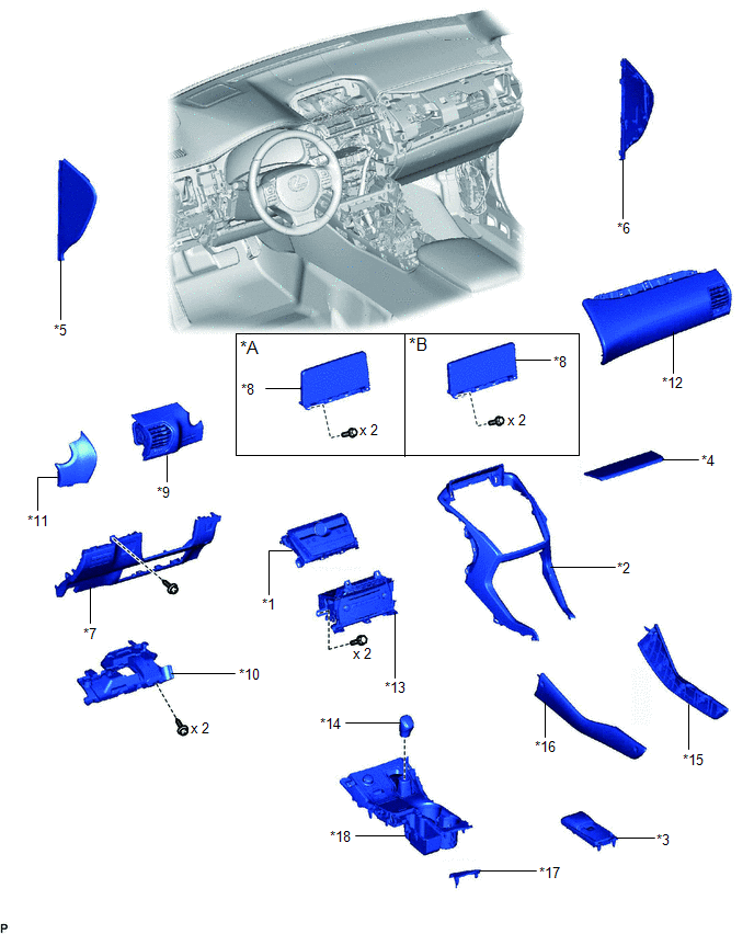
| *A | for 8 Inch | *B | for 10.3 Inch |
| *1 | AIR CONDITIONING CONTROL ASSEMBLY | *2 | CENTER INSTRUMENT CLUSTER FINISH PANEL ASSEMBLY |
| *3 | CONSOLE ARMREST ASSEMBLY | *4 | INSTRUMENT PANEL FINISH PLATE |
| *5 | INSTRUMENT SIDE PANEL LH | *6 | INSTRUMENT SIDE PANEL RH |
| *7 | LOWER NO. 1 INSTRUMENT PANEL FINISH PANEL | *8 | MULTI-DISPLAY ASSEMBLY WITH BRACKET |
| *9 | NO. 1 INSTRUMENT PANEL SAFETY PAD SUB-ASSEMBLY | *10 | NO. 1 INSTRUMENT PANEL UNDER COVER SUB-ASSEMBLY |
| *11 | NO. 1 SWITCH HOLE BASE | *12 | NO. 2 INSTRUMENT PANEL SAFETY PAD SUB-ASSEMBLY |
| *13 | RADIO RECEIVER ASSEMBLY WITH BRACKET | *14 | SHIFT LEVER KNOB SUB-ASSEMBLY |
| *15 | UPPER NO. 1 CONSOLE PANEL GARNISH | *16 | UPPER NO. 2 CONSOLE PANEL GARNISH |
| *17 | UPPER REAR CONSOLE PANEL | *18 | UPPER REAR CONSOLE PANEL SUB-ASSEMBLY |
ILLUSTRATION
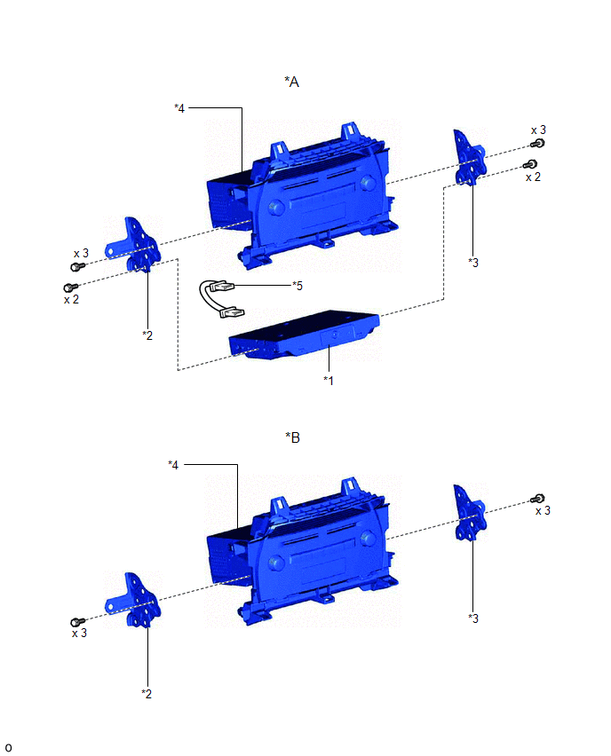
| *A | w/ Navigation System | *B | w/o Navigation System |
| *1 | NAVIGATION ECU | *2 | NO. 1 RADIO BRACKET |
| *3 | NO. 2 RADIO BRACKET | *4 | RADIO RECEIVER ASSEMBLY |
| *5 | NAVIGATION WIRE | - | - |
READ NEXT:
 Removal
REMOVAL PROCEDURE 1. REMOVE DECK BOARD ASSEMBLY Click here 2. REMOVE NO. 3 DECK BOARD SUB-ASSEMBLY Click here 3. REMOVE REAR DECK FLOOR BOX Click here 4. REMOVE DECK FLOOR BOX LH Click here 5.
Installation
INSTALLATION PROCEDURE 1. INSTALL RADIO RECEIVER ASSEMBLY 2. INSTALL NAVIGATION ECU Click here 3. INSTALL NO. 1 RADIO BRACKET (a) w/ Navigation System (1) Install the No. 1 radio bracket with the 5
SEE MORE:
Installation
INSTALLATION PROCEDURE 1. INSTALL NO. 3 BATTERY SERVICE COVER BOARD (a) for Power Seat: Connect the wire harness clamp and power seat switch connector. (b) Attach the 2 claws and install the No. 3 battery service cover board. (c) Install the 2 clips. 2. INSTALL NO. 2 BATTERY SERVICE COVER BOARD HINT
Installation
INSTALLATION CAUTION / NOTICE / HINT HINT:
Use the same procedure for the RH and LH sides.
The procedure listed below is for the LH side.
PROCEDURE 1. INSTALL SIDE AIRBAG SENSOR ASSEMBLY LH (a) Check that the power switch is off. (b) Check that the cable is disconnected from the negative (-)
