Lexus NX: Components
Lexus NX Service Manual / Vehicle Interior / Seat Belt / Seat Belt Warning Light (for Rear Side) / Components
COMPONENTS
ILLUSTRATION
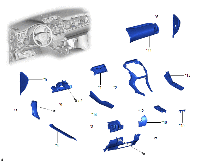
| *1 | AIR CONDITIONING CONTROL ASSEMBLY (SEAT BELT WARNING LIGHT) | *2 | CENTER INSTRUMENT CLUSTER FINISH PANEL ASSEMBLY |
| *3 | COWL SIDE TRIM BOARD LH | *4 | DOOR SCUFF PLATE ASSEMBLY LH |
| *5 | INSTRUMENT SIDE PANEL LH | *6 | INSTRUMENT SIDE PANEL RH |
| *7 | LOWER NO. 1 INSTRUMENT PANEL FINISH PANEL | *8 | NO. 1 INSTRUMENT PANEL SAFETY PAD SUB-ASSEMBLY |
| *9 | NO. 1 INSTRUMENT PANEL UNDER COVER SUB-ASSEMBLY | *10 | NO. 1 SWITCH HOLE BASE |
| *11 | NO. 2 INSTRUMENT PANEL SAFETY PAD SUB-ASSEMBLY | *12 | REAR CONSOLE ARMREST ASSEMBLY |
| *13 | UPPER NO. 1 CONSOLE PANEL GARNISH | *14 | UPPER NO. 2 CONSOLE PANEL GARNISH |
| *15 | UPPER REAR CONSOLE PANEL | - | - |
READ NEXT:
 Removal
REMOVAL PROCEDURE 1. REMOVE MULTI-DISPLAY ASSEMBLY Click here 2. REMOVE DOOR SCUFF PLATE ASSEMBLY LH Click here 3. REMOVE COWL SIDE TRIM BOARD LH Click here 4. REMOVE REAR CONSOLE ARMREST ASS
Inspection
INSPECTION PROCEDURE 1. INSPECT AIR CONDITIONING CONTROL ASSEMBLY (SEAT BELT WARNING LIGHT) (for Rear Side) (a) Check the seat belt warning light illumination. OK: Measurement Condition Speci
Installation
INSTALLATION PROCEDURE 1. INSTALL AIR CONDITIONING CONTROL ASSEMBLY (SEAT BELT WARNING LIGHT) (a) Connect the 2 connectors. (b) Attach the 6 clips to install the air conditioning control assembly (
SEE MORE:
Diagnosis System
DIAGNOSIS SYSTEM DESCRIPTION When troubleshooting OBD II (On-Board Diagnostics) vehicles, the Techstream (complying with SAE J1978) must be connected to the DLC3 (Data Link Connector 3) of the vehicle. Various data in the vehicle's ECM (Engine Control Module) can be then read. OBD II regulations re
One or more Power Seat Motors do not Operate
DESCRIPTION Signals are input into the front power seat switch LH. The built-in ECU manages the signals received from the front power seat switch LH, and operates each motor. If the front power seat switch LH receives more than 2 motor operation signals, the motor is stopped. Manual operation is res
© 2016-2024 Copyright www.lexunx.com
