Lexus NX: Components
COMPONENTS
ILLUSTRATION
.png)
| *1 | DECK FLOOR BOX LH | *2 | NO. 3 DECK BOARD SUB-ASSEMBLY |
| *3 | REAR DECK FLOOR BOX | *4 | NEGATIVE AUXILIARY BATTERY TERMINAL |
.png) | N*m (kgf*cm, ft.*lbf): Specified torque | - | - |
ILLUSTRATION
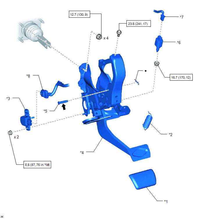
| *1 | BRAKE PEDAL PAD | *2 | BRAKE PEDAL RETURN SPRING |
| *3 | BRAKE PEDAL STROKE SENSOR ASSEMBLY | *4 | BRAKE PEDAL SUPPORT ASSEMBLY |
| *5 | PUSH ROD PIN | *6 | STOP LIGHT SWITCH ASSEMBLY |
| *7 | STOP LIGHT SWITCH CONNECTOR | *8 | BRAKE PEDAL STROKE SENSOR CONNECTOR |
| | N*m (kgf*cm, ft.*lbf): Specified torque | ● | Non-reusable part |
.png) | Lithium soap base glycol grease | - | - |
READ NEXT:
 Removal
REMOVAL PROCEDURE 1. PRECAUTION CAUTION: Be sure to read Precoution thoroughly before serving. Click here NOTICE: After turning the power switch off, there may be a waiting time before disconnecting
Adjustment
ADJUSTMENT PROCEDURE 1. INSPECT AND ADJUST BRAKE PEDAL HEIGHT (a) Check the brake pedal height. *1 Brake Pedal Pad - - *a Brake Pedal Height *b Measuring Plane of Floor Panel Br
Installation
INSTALLATION PROCEDURE 1. INSTALL BRAKE PEDAL PAD (a) Install the brake pedal pad to the brake pedal support assembly. 2. INSTALL BRAKE PEDAL STROKE SENSOR ASSEMBLY Click here 3. INSTALL BRAKE PEDAL
SEE MORE:
Tilt and Telescopic Manual Switch Circuit Malfunction (B2603)
DESCRIPTION Different voltage values are sent to the multiplex tilt and telescopic ECU by operating the tilt and telescopic switch. The multiplex tilt and telescopic ECU then judges which motor and in which direction that motor should operate based on the voltage value. DTC No. Detection Item
Open Circuit in Stop Light Switch Circuit (C1249)
DESCRIPTION The skid control ECU (brake booster with master cylinder assembly) receives the stop light switch assembly signal and detects the brake pedal operation status. The skid control ECU (brake booster with master cylinder assembly) has an open detection circuit, which stores this DTC if it de
© 2016-2024 Copyright www.lexunx.com
