Lexus NX: Removal
REMOVAL
PROCEDURE
1. PRECAUTION
CAUTION:
Be sure to read Precoution thoroughly before serving.
Click here .gif)
NOTICE:
After turning the power switch off, there may be a waiting time before disconnecting the negative (-) auxiliary battery terminal.
Click here
2. REMOVE NO. 3 DECK BOARD SUB-ASSEMBLY
Click here
3. REMOVE REAR DECK FLOOR BOX
Click here
4. REMOVE DECK FLOOR BOX LH
Click here
5. DISCONNECT NEGATIVE AUXILIARY BATTERY TERMINAL
CAUTION:
- Wait at least 90 seconds after disconnecting the cable from the negative (-) auxiliary battery terminal to disable the SRS system.
- If the airbag deploys for any reason. it may cause a serious accident.
(a) Loosen the nut and disconnect the negative (-) auxiliary battery terminal.
6. REMOVE LOWER NO. 1 INSTRUMENT PANEL AIRBAG ASSEMBLY
Click here
7. REMOVE UPPER INSTRUMENT PANEL SUB-ASSEMBLY
Click here
8. REMOVE STOP LIGHT SWITCH ASSEMBLY
Click here
9. REMOVE BRAKE PEDAL RETURN SPRING
(a) Remove the brake pedal return spring from the brake pedal support assembly.
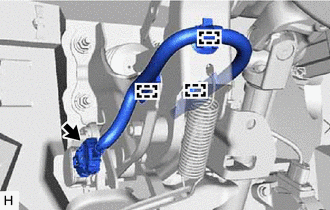
10. REMOVE PUSH ROD PIN
(a) Remove the clip from the push rod pin.
(b) Remove the push rod pin from the push rod clevis.
11. REMOVE BRAKE PEDAL SUPPORT ASSEMBLY
| (a) Remove the brake pedal support reinforcement set bolt. |
|
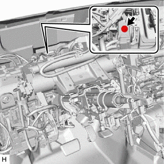
| (b) Disconnect the connector from the brake pedal stroke sensor assembly. |
|
(c) Disconnect the 3 clamps from the brake pedal support assembly.
(d) Remove the 4 nuts and brake pedal support assembly.
12. REMOVE BRAKE PEDAL STROKE SENSOR ASSEMBLY
Click here
13. REMOVE BRAKE PEDAL PAD
(a) Remove the brake pedal pad from the brake pedal support assembly.
READ NEXT:
 Adjustment
ADJUSTMENT PROCEDURE 1. INSPECT AND ADJUST BRAKE PEDAL HEIGHT (a) Check the brake pedal height. *1 Brake Pedal Pad - - *a Brake Pedal Height *b Measuring Plane of Floor Panel Br
Installation
INSTALLATION PROCEDURE 1. INSTALL BRAKE PEDAL PAD (a) Install the brake pedal pad to the brake pedal support assembly. 2. INSTALL BRAKE PEDAL STROKE SENSOR ASSEMBLY Click here 3. INSTALL BRAKE PEDAL
SEE MORE:
Brake Hydraulic Pressure Malfunction (C164F)
DESCRIPTION When a malfunction signal sent from the brake booster with master cylinder assembly (skid control ECU) via CAN communication is detected by the clearance warning ECU assembly, DTC C164F is stored. DTC No. Detection Item DTC Detection Condition Trouble Area C164F Brake Hydr
Cold Start Ignition Timing Performance (P050B)
MONITOR DESCRIPTION This monitor will run when the engine is started at an engine coolant temperature of -10 to 50°C (14 to 122°F). The DTC is stored after the engine idles for 13 seconds (2 trip detection logic). The DTC is designed to monitor the ignition timing at cold start. When the engine is
