Lexus NX: Diagnosis System
DIAGNOSIS SYSTEM
DESCRIPTION
The ECU stores DTCs when malfunctions occur.
The diagnostic system allows for reading of the DTCs from the DLC3.
Use the Techstream to check for malfunctions and perform repairs.
CHECK DLC3
(a) Check the DLC3.
Click here .gif)
INSPECT AUXILIARY BATTERY VOLTAGE
(a) Measure the auxiliary battery voltage.
Standard voltage:
11 to 14 V (power switch off)
If the voltage is below 11 V, recharge or replace the auxiliary battery.
SELF-DIAGNOSTIC MODE (USING TECHSTREAM)
(a) Connect the Techstream to the DLC3.
(b) Turn the power switch on (IG).
(c) Turn the Techstream on.
(d) Enter the following menus: Body Electrical / Entry&Start / Utility / Wireless Door Lock Diagnosis Mode.
Body Electrical > Smart Access > Utility| Tester Display |
|---|
| Wireless Door Lock Diagnosis Mode |
(e) Proceed to the next step in accordance with the prompts on the Techstream screen.
(f) Check that the system has switched to self-diagnostic mode by checking the wireless door lock buzzer output pattern.
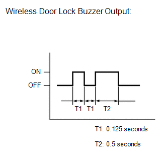
(g) Check the diagnostic outputs when an electrical key transmitter sub-assembly switch is pressed. The diagnostic outputs can be checked by the interior light and wireless door lock buzzer patterns.
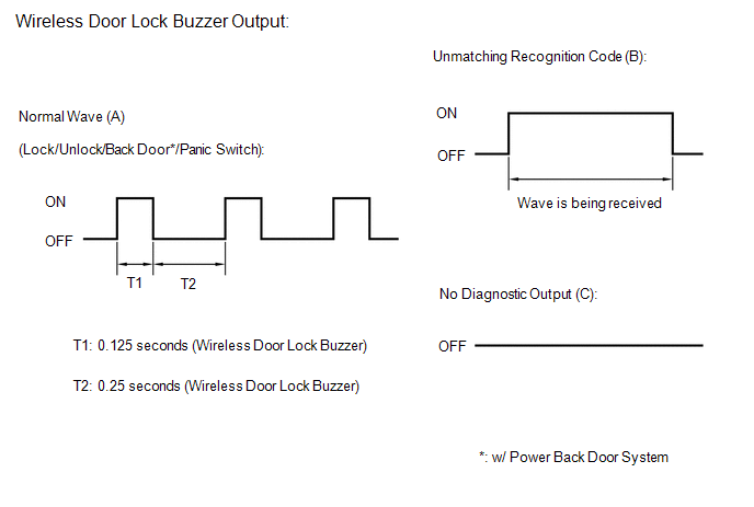 Result
 | Wireless Door Lock Buzzer Output | Suspected Area |
|---|---|
| A | Normal (No malfunction) |
| B | Register wireless code |
| C | Wave interference or malfunction of a related component |
READ NEXT:
 Dtc Check / Clear
DTC CHECK / CLEAR CHECK DTC (a) Connect the Techstream to the DLC3. (b) Turn the power switch on (IG). (c) Turn the Techstream on. (d) Enter the following menus: Body Electrical / Smart Access / Troub
Data List / Active Test
DATA LIST / ACTIVE TEST DATA LIST HINT: Using the Techstream to read the Data List allows the values or states of switches, sensors, actuators and other items to be read without removing any parts. Th
Diagnostic Trouble Code Chart
DIAGNOSTIC TROUBLE CODE CHART Wireless Door Lock Control System DTC No. Detection Item Link B1242 Wireless Door Lock Tuner Circuit Malfunction
SEE MORE:
Dtc Check / Clear
DTC CHECK / CLEAR NOTICE: When the diagnosis system is changed from normal mode to check mode or vice versa, all DTCs and freeze frame data recorded in normal mode are cleared. Before changing modes, always check and make a note of DTCs and freeze frame data. HINT:
DTCs which are stored in the EC
Removal
REMOVAL PROCEDURE 1. PRECAUTION CAUTION: Be sure to read Precoution thoroughly before serving. Click here NOTICE: After turning the power switch off, there may be a waiting time before disconnecting the negative (-) auxiliary battery terminal. Click here 2. REMOVE NO. 3 DECK BOARD SUB-ASSEMBLY C
