Lexus NX: Disassembly
DISASSEMBLY
CAUTION / NOTICE / HINT
NOTICE:
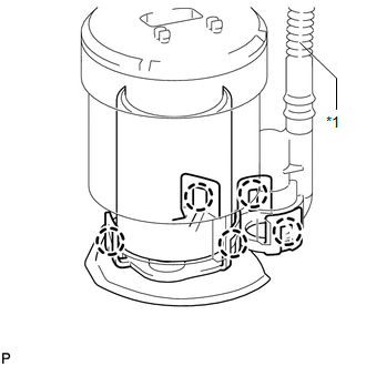
Do not try to remove the black nylon tube as it is welded to the fuel suction tube assembly.
Click here .gif)
PROCEDURE
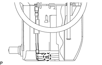
1. REMOVE NO. 1 FUEL SUB-TANK
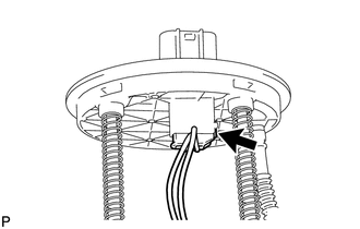
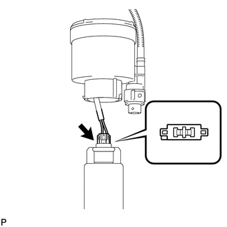
| (a) Disconnect the fuel pump harness connector. |
|
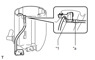
(b) Using needle nose pliers, remove the fuel tank pipe setting holder.
HINT:
Slightly lower the fuel suction plate sub-assembly to remove the fuel tank pipe setting holder.
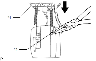
| *1 | Fuel Suction Plate Sub-assembly |
| *2 | Fuel Tank Pipe Setting Holder |
.png) | Lower |
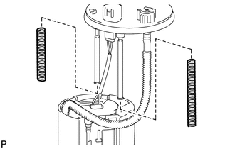
| (c) Remove the No. 2 fuel tank cushion and No. 3 fuel tank cushion from the fuel suction plate sub-assembly. |
|
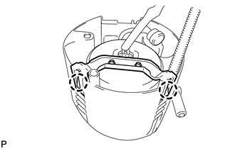
| (d) Using a screwdriver with its tip wrapped with protective tape, detach the 2 claws and remove the fuel filter assembly from the No. 1 fuel sub-tank. |
|
| (e) Detach the claw of the jet pump nozzle. |
|
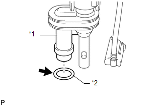
| (f) Using a screwdriver with protective tape wrapped around it, remove the jet pump from the No. 1 fuel sub-tank. HINT: Tape the screwdriver tip before use. |
|
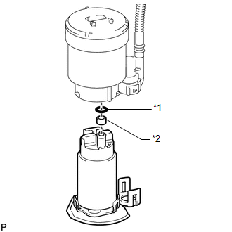
| (g) Remove the O-ring from the jet pump. |
|
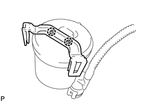
2. REMOVE NO. 1 FUEL SUCTION SUPPORT
| (a) Using needle-nose pliers, detach the 2 claws and remove the No. 1 fuel suction support from the fuel filter assembly. |
|
3. REMOVE FUEL PUMP ASSEMBLY WITH FILTER
| (a) Using a screwdriver with its tip wrapped with protective tape, detach the 5 claws and remove the fuel filter assembly from the fuel pump assembly with filter. NOTICE: When detaching the claws, do not disconnect the fuel main tube. |
|
| (b) Disconnect the fuel pump harness connector. |
|
| (c) Remove the O-ring from the fuel pump. |
|
(d) Remove the fuel pump spacer from the fuel pump.
READ NEXT:
 Inspection
INSPECTION PROCEDURE 1. INSPECT FUEL PUMP ASSEMBLY WITH FILTER (a) Check the resistance. (1) Measure the resistance according to the value(s) in the table below. Standard Resistance: Tester Con
Reassembly
REASSEMBLY CAUTION / NOTICE / HINT NOTICE: Do not try to remove the black nylon tube as it is welded to the fuel suction tube assembly. Click here HINT: Perform "Inspection After Repairs" after rep
Installation
INSTALLATION CAUTION / NOTICE / HINT HINT: Perform "Inspection After Repairs" after replacing the fuel pump. Click here PROCEDURE 1. INSTALL FUEL SUCTION TUBE ASSEMBLY (a) Install a new gasket onto
SEE MORE:
Components
COMPONENTS ILLUSTRATION *1 DECK FLOOR BOX LH *2 NO. 3 DECK BOARD SUB-ASSEMBLY *3 REAR DECK FLOOR BOX *4 NEGATIVE AUXILIARY BATTERY TERMINAL N*m (kgf*cm, ft.*lbf): Specified torque - - ILLUSTRATION *1 BATTERY SERVICE HOLE COVER *2 HYBRID BATTERY SERVICE PLU
Precaution
PRECAUTION TROUBLESHOOTING PRECAUTIONS (a) When there is a malfunction with terminal contact points or a problem with the installation of a part, reconnecting the connectors or removal/installation of the suspected parts may return the system to the normal condition either completely or temporarily.
