Lexus NX: Installation
INSTALLATION
CAUTION / NOTICE / HINT
HINT:
Perform "Inspection After Repairs" after replacing the fuel pump.
Click here .gif)
PROCEDURE
1. INSTALL FUEL SUCTION TUBE ASSEMBLY
(a) Install a new gasket onto the fuel suction tube assembly.
| (b) With the paint mark facing the top of the vehicle, connect the fuel hose to the fuel suction tube assembly and secure the hose with the clamp. |
|
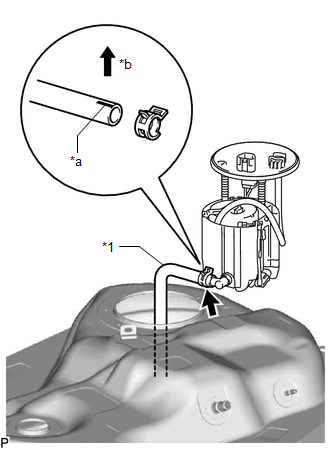
(c) Install the fuel suction tube assembly to the fuel tank assembly.
NOTICE:
Be careful not to damage the fuel suction tube assembly.
2. INSTALL FUEL TANK VENT TUBE SET PLATE
(a) Install the fuel tank vent tube set plate with the 8 bolts.
Torque:
6.0 N·m {61 kgf·cm, 53 in·lbf}
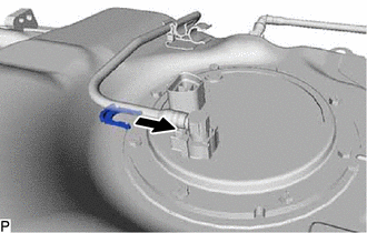
3. CONNECT FUEL TANK MAIN TUBE SUB-ASSEMBLY
(a) Connect the fuel tank main tube sub-assembly to the fuel suction plate sub-assembly, then install the tube joint clip.
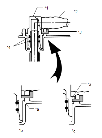
| *1 | Fuel Tube Joint |
| *2 | Fuel Tank Main Tube Sub-assembly |
| *3 | Tube Joint Clip |
| *4 | O-Ring |
| *a | Collar |
| *b | CORRECT |
| *c | INCORRECT |
- Check that there are no scratches or foreign objects on the connecting parts.
- Check that the fuel tube joint is inserted securely.
- Make sure that the fuel joint clip is above the flange of the fuel tank main tube sub-assembly.
- After installing the tube joint clip, make sure that the fuel tank main tube sub-assembly cannot be pulled out.
- Be careful not to damage the tube joint clip. If the tube joint clip is damaged, replace it.
4. INSTALL FUEL TANK ASSEMBLY
Click here
READ NEXT:
 Fuel Pump Ecu
ComponentsCOMPONENTS ILLUSTRATION *1 FUEL PUMP CONTROL ECU ASSEMBLY *2 PARKING BRAKE ECU ASSEMBLY N*m (kgf*cm, ft.*lbf): Specified torque - - RemovalREMOVAL PROCEDURE 1. REMO
Fuel Sender Gauge Assembly
ComponentsCOMPONENTS ILLUSTRATION *1 FUEL SENDER GAUGE ASSEMBLY - - N*m (kgf*cm, ft.*lbf): Specified torque - - RemovalREMOVAL PROCEDURE 1. REMOVE FUEL TANK ASSEMBLY Click he
SEE MORE:
Diagnosis System
DIAGNOSIS SYSTEM DESCRIPTION (a) Lighting system data and the Diagnostic Trouble Codes (DTCs) can be read from the Data Link Connector 3 (DLC3) of the vehicle. When the system seems to be malfunctioning, use the Techstream to check for malfunctions, and then perform repairs. CHECK DLC3 (a) Check the
Buzzer Circuit Short to Ground or Open (C1A4A14)
DESCRIPTION If the forward recognition camera detects an open or short to ground in the buzzer circuit, it will store DTC C1A4A14. DTC No. Detection Item DTC Detection Condition Trouble Area C1A4A14 Buzzer Circuit Short to Ground or Open The forward recognition camera detects an ope
