Lexus NX: Disassembly
DISASSEMBLY
PROCEDURE
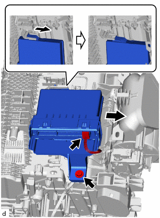
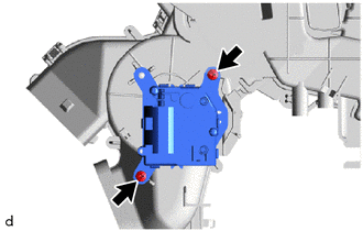
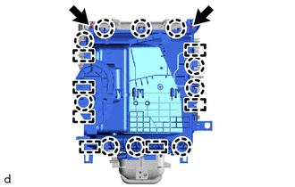
1. REMOVE AIR CONDITIONING RADIATOR ASSEMBLY
| (a) Disconnect the No. 1 blower damper servo sub-assembly connector. |
|
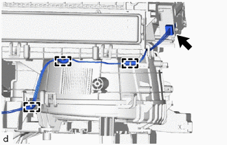
(b) Detach the 3 clamps and remove the air conditioning harness assembly.
| (c) Remove the 2 screws. |
|
(d) Detach the 2 claws and remove the air conditioning radiator assembly.
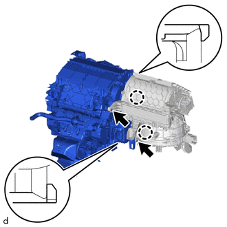
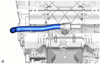
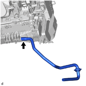
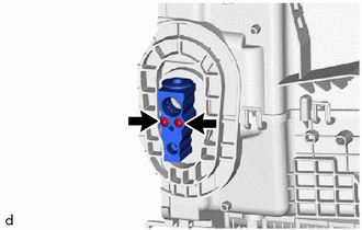
2. REMOVE ASPIRATOR
| (a) Remove the aspirator hose. |
|
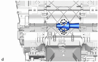
| (b) Detach the 2 claws and remove the aspirator. |
|
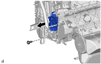
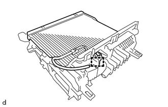
3. REMOVE AIR CONDITIONING AMPLIFIER ASSEMBLY
| (a) Disconnect the air conditioning amplifier assembly connector. |
|
(b) Remove the screw.
(c) Detach the guide and remove the air conditioning amplifier assembly as shown in the illustration.
4. REMOVE DRAIN COOLER HOSE
| (a) Remove the drain cooler hose. |
|
5. REMOVE AIR CONDITIONING HARNESS ASSEMBLY
(a) Disconnect the 3 connectors.
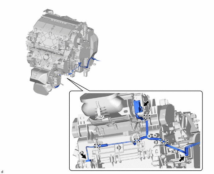
(b) Detach the 4 clamps and remove the air conditioning harness assembly.
6. REMOVE QUICK HEATER ASSEMBLY
| (a) Remove the screw and quick heater assembly. |
|
7. REMOVE NO. 2 AIR CONDITIONING RADIATOR DAMPER SERVO SUB-ASSEMBLY
| (a) Remove the 2 screws and No. 2 air conditioning radiator damper servo sub-assembly. |
|
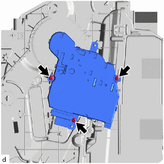
8. REMOVE NO. 1 AIR CONDITIONING RADIATOR DAMPER SERVO SUB-ASSEMBLY
| (a) Remove the 3 screws and No. 1 air conditioning radiator damper servo sub-assembly. |
|
9. REMOVE HEATER RADIATOR UNIT SUB-ASSEMBLY
| (a) Remove the screw. |
|
(b) Detach the 2 claws and remove the clamp.
| (c) Remove the heater radiator unit sub-assembly from the air conditioning radiator assembly. |
|

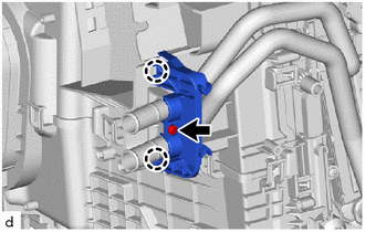
10. REMOVE COOLER EXPANSION VALVE
(a) Remove the cooling unit packing.
| (b) Using a 4 mm hexagon wrench, remove the 2 hexagon bolts and cooler expansion valve. |
|
11. REMOVE NO. 1 COOLER EVAPORATOR SUB-ASSEMBLY
| (a) Remove the 2 screws. |
|
(b) Detach the 10 claws and 7 guides, and remove the upper heater case.
| (c) Detach the clamp. |
|
(d) Remove the No. 1 cooler evaporator sub-assembly with the No. 1 cooler thermistor.
NOTICE:
When the No. 1 cooler evaporator sub-assembly is removed, make sure to install a new one. The No. 1 cooler evaporator sub-assembly cannot be reused.
(e) Remove the 2 O-rings from the No. 1 cooler evaporator sub-assembly.
12. REMOVE NO. 1 COOLER THERMISTOR
Click here .gif)
READ NEXT:
 Reassembly
REASSEMBLY PROCEDURE 1. INSTALL NO. 1 COOLER THERMISTOR Click here 2. INSTALL NO. 1 COOLER EVAPORATOR SUB-ASSEMBLY (a) Sufficiently apply compressor oil to 2 new O-rings and the fitting surface of t
Installation
INSTALLATION CAUTION / NOTICE / HINT HINT:
Use the same procedure for the RH and LH sides.
The procedure listed below is for the LH side.
A bolt without a torque specification is shown in the s
Ambient Temperature Sensor
ComponentsCOMPONENTS ILLUSTRATION *1 THERMISTOR ASSEMBLY (AMBIENT TEMPERATURE SENSOR) - - RemovalREMOVAL PROCEDURE 1. REMOVE FRONT BUMPER ASSEMBLY (a) for Sport Package: Click here (b
SEE MORE:
Problem Symptoms Table
PROBLEM SYMPTOMS TABLE HINT:
Use the table below to help determine the cause of problem symptoms. If multiple suspected areas are listed, the potential causes of the symptoms are listed in order of probability in the "Suspected Area" column of the table. Check each symptom by checking the suspect
Removal
REMOVAL PROCEDURE 1. REMOVE MULTI-DISPLAY ASSEMBLY Click here 2. REMOVE DOOR SCUFF PLATE ASSEMBLY LH Click here 3. REMOVE COWL SIDE TRIM BOARD LH Click here 4. REMOVE REAR CONSOLE ARMREST ASSEMBLY Click here 5. REMOVE UPPER REAR CONSOLE PANEL Click here 6. REMOVE UPPER NO. 1 CONSOLE P
