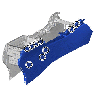
Lexus NX: Disassembly
DISASSEMBLY
PROCEDURE
1. REMOVE CONSOLE COMPARTMENT DOOR SUB-ASSEMBLY
| (a) Remove the 4 screws and console compartment door sub-assembly. |
|
2. REMOVE NO. 3 BOX PANEL
| (a) Detach the 2 clips and 2 claws, 3 guides and remove the No. 3 box panel. |
|
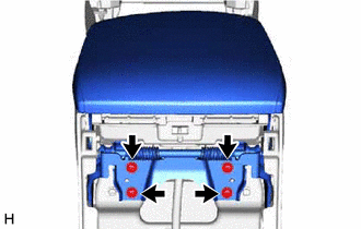
3. REMOVE CONSOLE BOX PLATE
(a) Using a screwdriver, detach the 4 claws and remove the 2 console box plates.
HINT:
Tape the screwdriver tip before use.
.png) | Protective Tape |
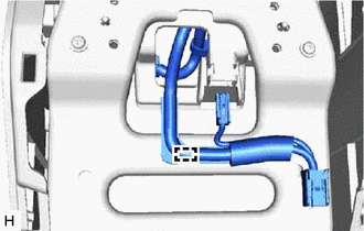
4. REMOVE MOBILE WIRELESS CHARGER CRADLE ASSEMBLY (w/ Wireless Charger)
Click here .gif)
5. REMOVE CONSOLE BOX ILLUMINATION LIGHT ASSEMBLY (w/ Wireless Charger)
(a) Disconnect the connector.
| | Protective Tape |
(b) Using a screwdriver, detach the 2 claws and remove the console box illumination light assembly.
HINT:
Tape the screwdriver tip before use.
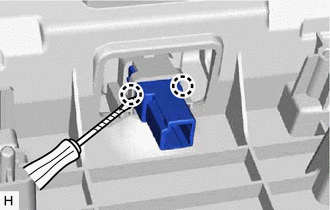
6. REMOVE CONSOLE BOX WIRE (w/ Wireless Charger)
| (a) Detach the clamp and remove the console box wire. |
|
7. REMOVE CONSOLE BOX WIRE (w/o Wireless Charger)
| (a) Remove the 4 screws and disconnect the bracket. |
|
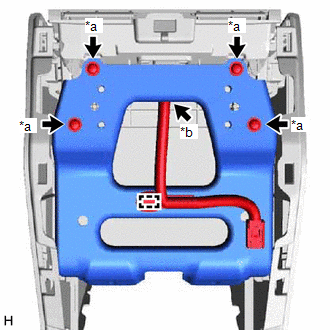
(b) Disconnect the connector and detach the clamp and remove the console box wire.
8. REMOVE CONSOLE BOX ILLUMINATION LIGHT ASSEMBLY (w/o Wireless Charger)
(a) Using a screwdriver, detach the 2 claws and remove the console box illumination light assembly.
HINT:
Tape the screwdriver tip before use.
| | Protective Tape |
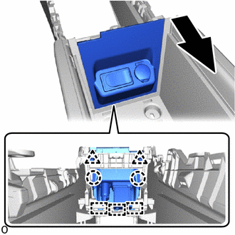
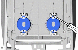
9. REMOVE NO. 2 BOX SIDE PANEL
| (a) Detach the 9 claws and remove the No. 2 box side panel. |
|
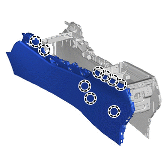
10. REMOVE NO. 1 BOX SIDE PANEL
| (a) Detach the 9 claws and remove the No. 1 box side panel. |
|
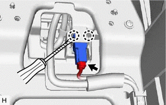
11. REMOVE SHIFTING HOLE COVER SUB-ASSEMBLY
(a) Using a screwdriver, detach the 7 claws and remove the shifting hole cover sub-assembly.
HINT:
Tape the screwdriver tip before use.
| | Protective Tape |
12. REMOVE SHIFT POSITION INDICATOR
| (a) Remove the 2 screws and shift position indicator. |
|
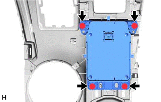
13. REMOVE INTEGRATION CONTROL AND PANEL ASSEMBLY
| (a) Remove the 2 screws and the integration control and panel assembly. |
|
14. REMOVE REMOTE OPERATION CONTROLLER ASSEMBLY
| (a) Remove the 4 screws and remote operation controller assembly. |
|
15. REMOVE CONSOLE COMPARTMENT BOX
| (a) Remove the 2 console compartment boxs. |
|
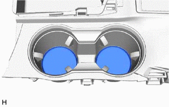
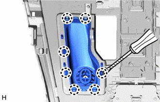
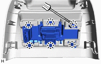
16. REMOVE CONSOLE CUP HOLDER BOX SUB-ASSEMBLY
(a) Using a screwdriver, detach the 10 claws and remove the cup holder rail.
HINT:
Tape the screwdriver tip before use.
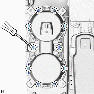
| | Protective Tape |
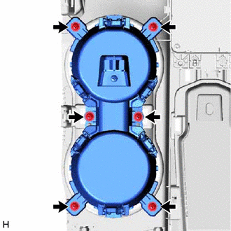
| (b) Remove the 6 screws and console cup holder box sub-assembly. |
|
17. REMOVE CONSOLE ARMREST LID
| (a) Remove the console armrest lid. |
|
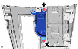
18. REMOVE CONSOLE BOX POCKET SUB-ASSEMBLY
| (a) Remove the 4 screws and console box pocket sub-assembly. |
|
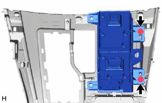
19. REMOVE CONSOLE BOX REGISTER ASSEMBLY
| (a) Remove the 6 screws and console box register assembly together with the duct. |
|
| (b) Disconnect the console box register assembly from the duct. |
|
20. REMOVE CIGARETTE LIGHTER COVER
(a) Using a screwdriver, detach the 6 claws and remove the cigarette lighter cover.
HINT:
Tape the screwdriver tip before use.
| | Protective Tape |
21. REMOVE REFRESHING SEAT SWITCH (w/ Rear Seat Heater)
Click here
READ NEXT:
 Installation
INSTALLATION CAUTION / NOTICE / HINT HINT: A bolt without a torque specification is shown in the standard bolt chart. Click here PROCEDURE 1. INSTALL CONSOLE BOX ASSEMBLY (a) Attach the 4 guides to
Components
COMPONENTS ILLUSTRATION *1 COWL SIDE TRIM BOARD LH *2 DOOR SCUFF PLATE ASSEMBLY LH *3 FRONT FLOOR CARPET ASSEMBLY *4 NO. 4 DASH PANEL INSULATOR PAD (FRONT FLOOR FOOTREST)
SEE MORE:
Abnormal Zero Point of Steering Angle Sensor (C1290)
DESCRIPTION The skid control ECU (brake booster with master cylinder assembly) acquires the steering sensor zero point every time the power switch is turned on (READY) and the vehicle is driven at 35 km/h (22 mph) or more for approximately 5 seconds. The skid control ECU (brake booster with master c
Installation
INSTALLATION PROCEDURE 1. INSTALL OCCUPANT DETECTION ECU (a) Attach the claw to install the occupant detection ECU. NOTICE: If the occupant detection ECU has been dropped, or there are any cracks, dents or other defects in the case or connector, replace the occupant detection ECU with a new one. (b)
